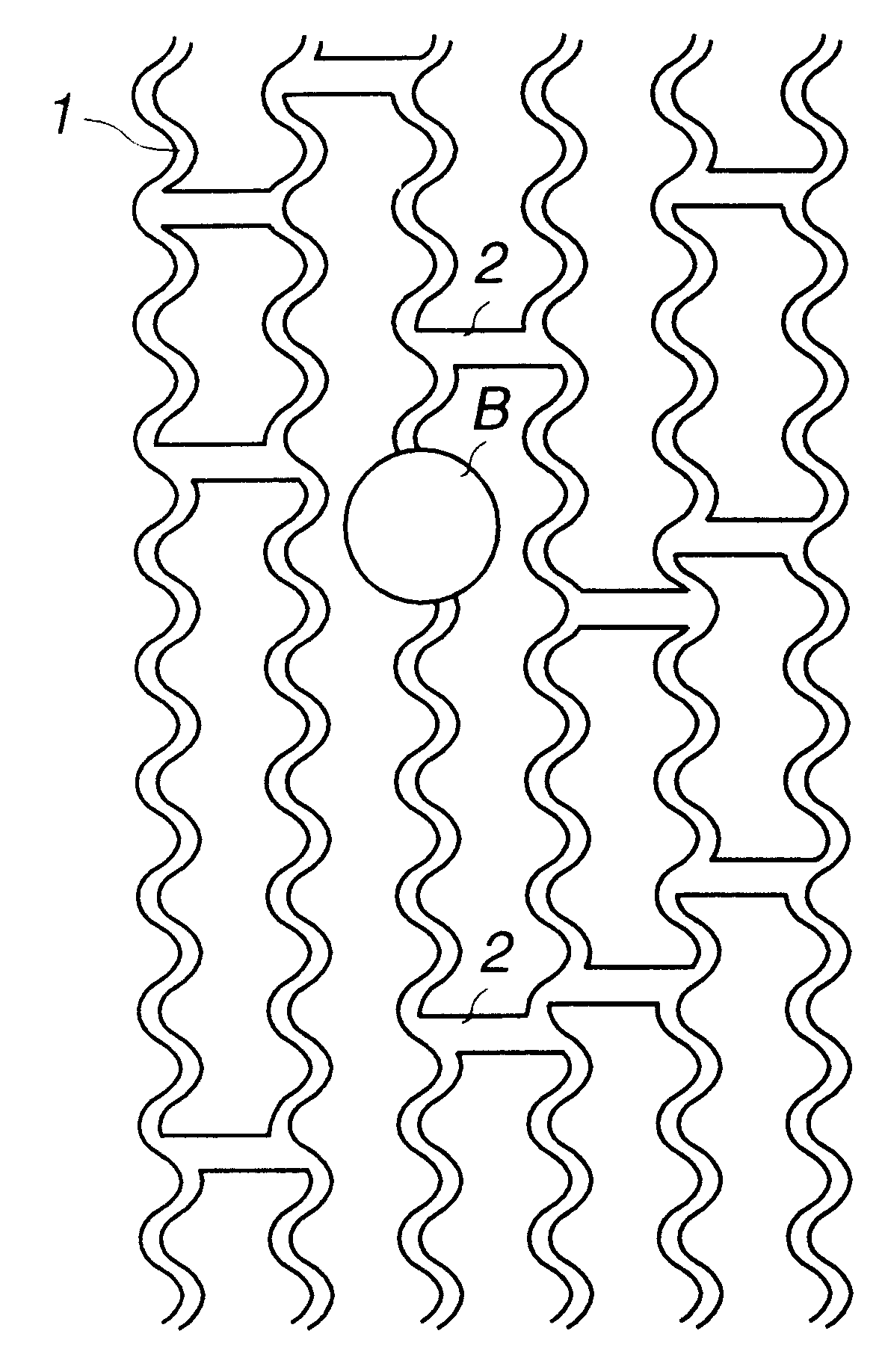
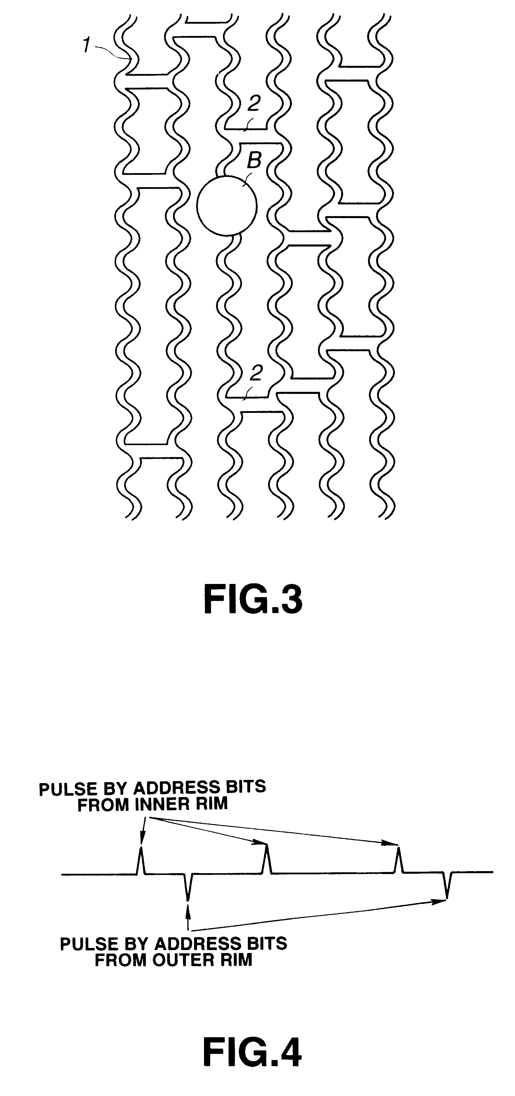
Optical recording medium with wobbled grooves and interconnecting pits
a technology of optical recording medium and groove, which is applied in the direction of optical recording/reproducing/erasing methods, instruments, disposition/mounting of heads, etc., can solve the problems of insufficient above-mentioned accuracy, obstruction of rotational control of discs, and inability to properly demodulate address information
- Summary
- Abstract
- Description
- Claims
- Application Information
AI Technical Summary
Benefits of technology
Problems solved by technology
Method used
Image
Examples
first embodiment
An optical disc of the present embodiment is a write-once type disc, 12 cm in diameter, having a recording film of an organic dye on which recording can be done using a laser beam having a wavelength of 635 nm.
The disc is formed of polycarbonate and is produced by injection molding with a guide groove and a land between neighboring turns of the guide groove.
The groove is approximately 0.25 .mu.m in width and approximately 70 nm in depth and is formed as a continuous spiral groove from the inner rim to the outer rim, with the groove interval or track pitch of approximately 0.74 .mu.m.
The wobbled signal of a sole frequency is recorded as the information for controlling the rpm of the disc and the clock frequency of the recording signal. The wobbling means slight meandering of the groove in the radial direction of the disc. In the present embodiment, the meandering width is 20 nm and the meandering period is approximately 30 .mu.m. Therefore, if the disc is rotated at a linear velocity...
second embodiment
In the present embodiment, various combinations of the wobbled pits are explained.
In a first example, wobbling of a sole frequence and pits having a integer number relation with respect to the frequency of the wobbled signal is explained.
The signal obtained in this case is as shown in FIG. 8, from which it is seen that pit signals Sp are detected at an interval equal to an integer times the period Tw of the wobbled signal Sw, that is at an interval equal to an integer times the pit period Tp.
In a second example, pits are formed in phase with the modulated wobbled signal. In the present example, pits are formed at positions proximate to the neighboring groove, corresponding to the maximum wobbling. The pit signals Sp are positioned at apices of the wobbled signal Sw and pits are detected based only of the signal level of the pit signal Sp, as shown in FIG. 9.
In FIG. 9, the pit signal Sp is generated by the pit formed on the inner rim side of the groove during tracking. On the other h...
PUM
| Property | Measurement | Unit |
|---|---|---|
| wavelength | aaaaa | aaaaa |
| wobbling frequency | aaaaa | aaaaa |
| diameter | aaaaa | aaaaa |
Abstract
Description
Claims
Application Information
 - R&D
- Intellectual Property
- Life Sciences
- Materials
- Tech Scout
- Unparalleled Data Quality
- Higher Quality Content
- 60% Fewer Hallucinations
Browse by: Latest US Patents, China's latest patents, Technical Efficacy Thesaurus, Application Domain, Technology Topic, Popular Technical Reports.
© 2025 PatSnap. All rights reserved.Legal|Privacy policy|Modern Slavery Act Transparency Statement|Sitemap|About US| Contact US: help@patsnap.com


