Block connector splitting in logic block of a field programmable gate array

a logic block and gate array technology, applied in the field of block connector splitting in the logic block, can solve the problems that the reprogrammable sram bit cannot be provided to connect routing resources, and the place and route of nets in the sram based fpga are difficul

Inactive Publication Date: 2001-09-04
MICROSEMI SOC
View PDF3 Cites 15 Cited by
  • Summary
  • Abstract
  • Description
  • Claims
  • Application Information

AI Technical Summary

Problems solved by technology

Due to the area required for an SRAM bit, a reprogrammble SRAM bit cannot be provided to connect routing resources to each other and the logic elements at every desired location.
Without a high degree of symmetry in the architecture, the SRAM memory bit depopulatio

Method used


Image

  • Block connector splitting in logic block of a field programmable gate array
  • Block connector splitting in logic block of a field programmable gate array
  • Block connector splitting in logic block of a field programmable gate array

Examples


Embodiment Construction

Those of ordinary skill in the art will realize that the following description of the present invention is illustrative only and not in any way limiting. Other embodiments of the invention will readily suggest themselves to such skilled persons.

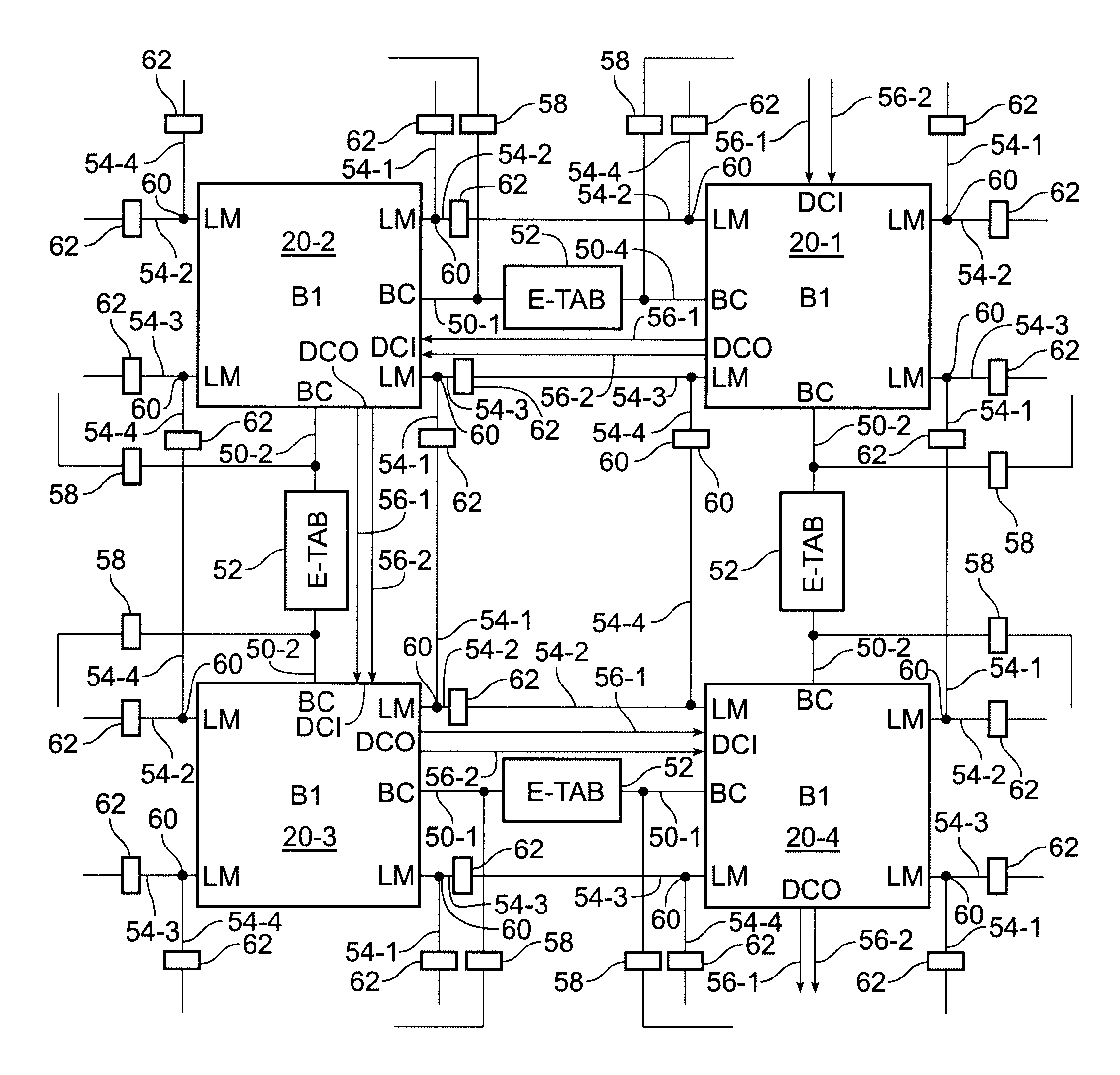
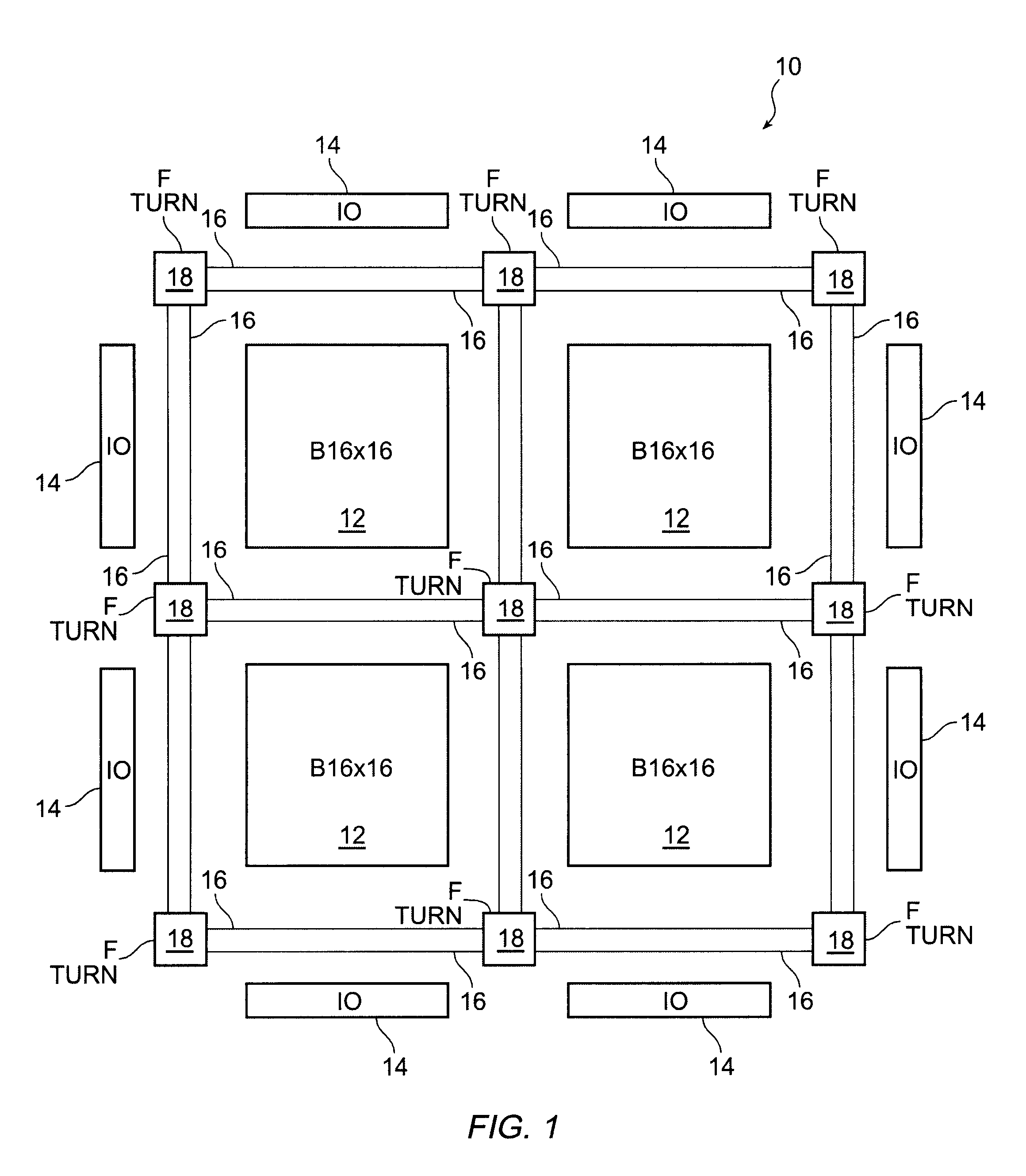
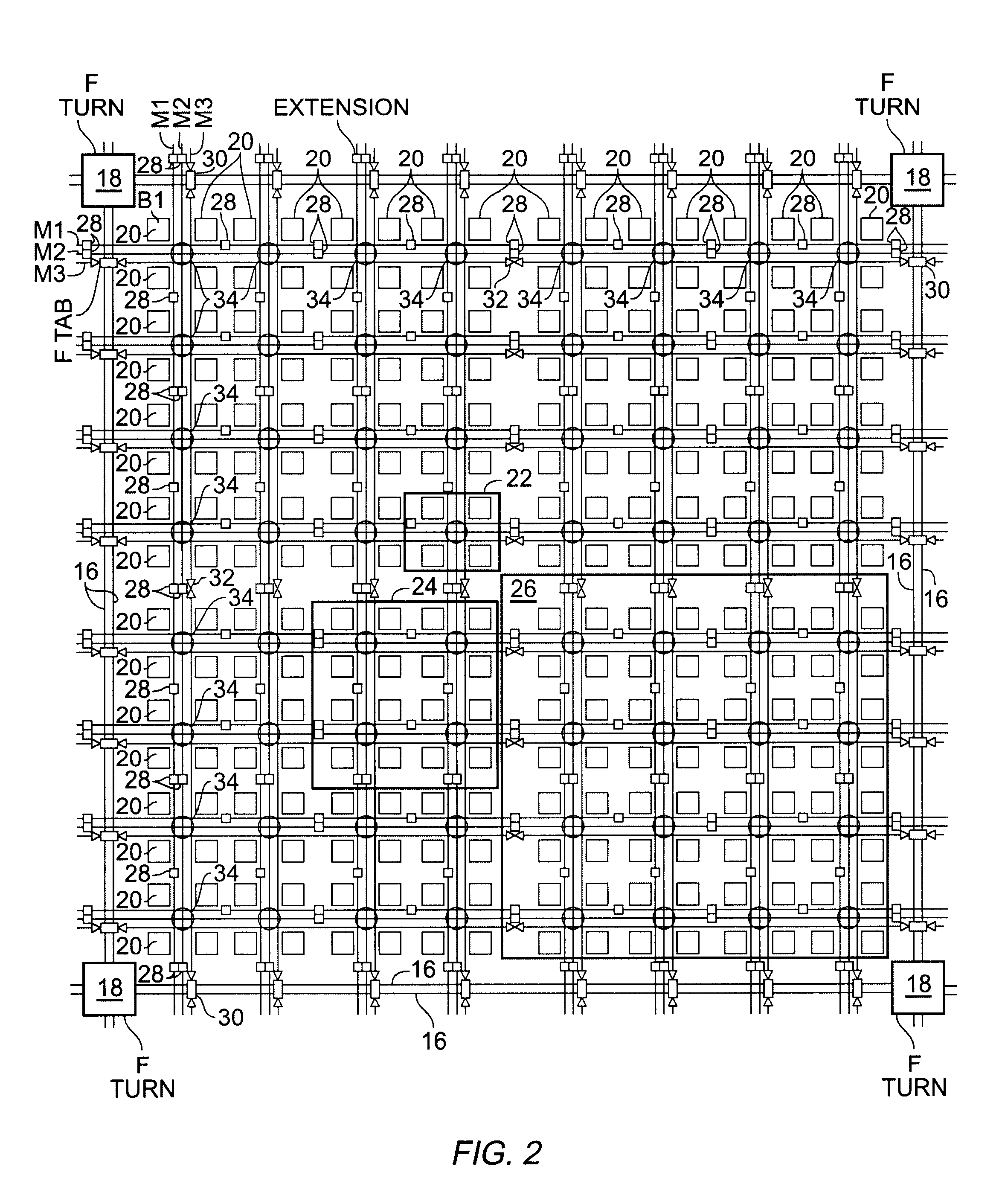
The present invention is directed to aspects of a semi-hierarchical architecture implemented in an FPGA having top, middle and low levels. In a semi-hierarchical architecture according to the present invention, the three levels of the architecture may be coupled to one another as in a hierarchy or the routing resources in each of the three levels may be extended to similar architectural groups in the same level of the architecture. The semi-hierarchical nature of the FPGA architecture according to the present invention significantly improves the place and route of nets or circuits in the lowest level of the architecture and in the connection of these nets to higher levels in the semi-hierarchical architecture. To better understand the present...


PUM


Abstract

An FPGA architecture has top, middle and low levels. The top level of the architecture is an array of the B16x16 tiles arranged in a rectangular array and enclosed by I/O blocks on the periphery. On each of the four sides of a B16x16 tile, and also associated with each of the I/O blocks is a freeway routing channel. A B16x16 tile in the middle level of hierarchy is a sixteen by sixteen array of B1 blocks. The routing resources in the middle level of hierarchy are expressway routing channels M1, M2, and M3 including groups of interconnect conductors. At the lowest level of the semi-hierarchical FPGA architecture, there are block connect (BC) routing channels, local mesh (LM) routing channels, and direct connect (DC) interconnect conductors to connect the logic elements to further routing resources. Within the B1 block, a horizontal BC routing channel is disposed between two upper and two lower clusters of devices, and a vertical BC routing channel is disposed between two clusters of devices on the left side of the B1 block and two clusters of devices on the right side of the B1 block. The BC routing channel forms intersections with the inputs and outputs of the devices in the clusters. The horizontal BC routing channel forms a first diagonally hardwired connection with a routing channel that effectively sends the horizontal BC routing channel in a vertical direction. A second diagonally hardwired connection pairwise shorts the horizontal and vertical BC routing channels to provide dual accessibility to the logic resources in the B1 block from more than one side. Disposed between the first diagonally hardwired connection and the second diagonally hardwired connection is a BC splitting extension which provides a programmable one-to-one coupling between the interconnect conductors of the horizontal BC routing channel on either side of the BC splitting extension.

Description

SPECIFICATION1. Field of the InventionThe present invention relates to a field programmable gate array (FPGA) architecture. More particularly, the present invention relates to the routing resources within a logic block for increasing the routing flexibility in an FPGA architecture .2. The Background ArtIn the FPGA art, both antifuse based programmable architectures and SRAM based reprogrammable architectures are well known. In an FPGA, the logic elements in the gate array are connected together by routing resources to form a desired integrated circuit. The routing resources are connected to each other and to the logic elements in the gate array by programmable elements. In a antifuse based device, the number of the programmable elements far exceeds the number of elements in an SRAM based device because the area required for an antifuse is much smaller than an SRAM bit. Despite this space disadvantage of an SRAM based device, SRAM based devices are implemented because they are reprog...

Claims


Application Information

Patent Timeline
IPC IPC(8): H03K19/177
CPCH03K19/17736H03K19/17728
Inventor KAPTANOGLU, SINAN
Owner MICROSEMI SOC
Why Eureka
Try Eureka