Optical cross connect unit, optical add-drop multiplexer, light source unit, and adding unit

a technology of optical cross-connecting and light source, applied in the direction of electromagnetic repeaters, transmission monitoring, instruments, etc., can solve the problems of system lack of flexibility, and troublesome management of light source itsel

Inactive Publication Date: 2001-09-04
FUJITSU LTD
View PDF9 Cites 69 Cited by
  • Summary
  • Abstract
  • Description
  • Claims
  • Application Information

AI Technical Summary

Problems solved by technology

There is a problem which arises with the related optical cross connect unit 100', however, in that the equipment of 16.times.8.times.8 LD light sources becomes necessary and the management of the light sources themselves becomes troublesome.
In addition, difficulty is encountered to dynamically switch the wavelengths according to the circumstances and the transmission is made with predetermined wavelengths, with the result that its system lacks flexibility.
Furthermore, similarly, the optical ADM 400'-1 is required to be equipped with 8.times.5 LD light sources, with the result that the management of the light sources themselves becomes troublesome.
Although a reductancy arrangement such as the preparation of spare l

Method used


Image

  • Optical cross connect unit, optical add-drop multiplexer, light source unit, and adding unit
  • Optical cross connect unit, optical add-drop multiplexer, light source unit, and adding unit
  • Optical cross connect unit, optical add-drop multiplexer, light source unit, and adding unit

Examples


first embodiment

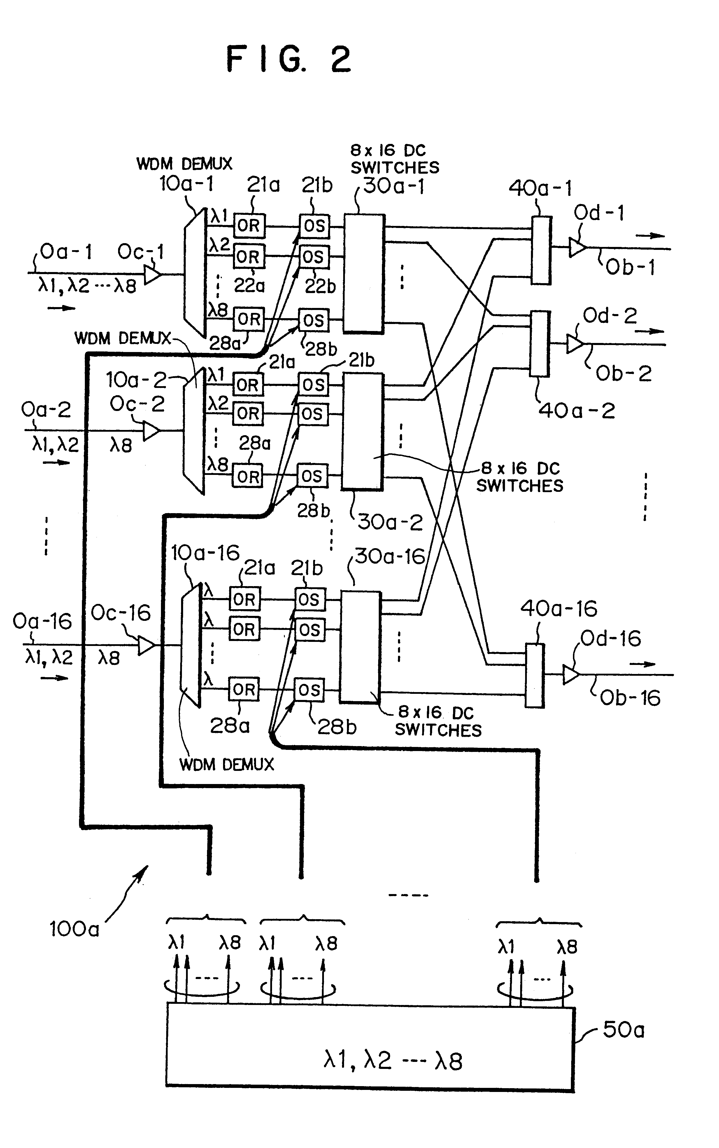
FIG. 2 is a block diagram showing an optical cross connect unit 100a according to this invention. As shown in FIG. 2, the optical cross connect unit 100a is, at its inlet and outlet sides, coupled to 16 optical fibers 0a-1 to 0a-16 and 0b-1 to 0b-16.

Each of the optical fibers 0a-1 to 0a-16 and 0b-1 to 0b-16 is made to forward 8 kinds of wavelengths .lambda.1 to .lambda.8 different from each other.

Taking into consideration that 16 kinds of wavelength multiplexed signals are transmitted through 16 optical fibers, for the convenience of description, the optical fiber 0a-1 and the optical fiber 0b-1 are related to each other and taken as 1 system (which will be referred hereinafter to as "#1"). Accordingly, since 16 optical fibers are connected to each of the inlet and outlet sides of the optical cross connect unit 100a, the optical cross connect unit 100a contains 16 systems in total.

A description will be made hereinbelow in terms of a wavelength multiplexed signal coming in through th...

second embodiment

(c) Description of Second Embodiment

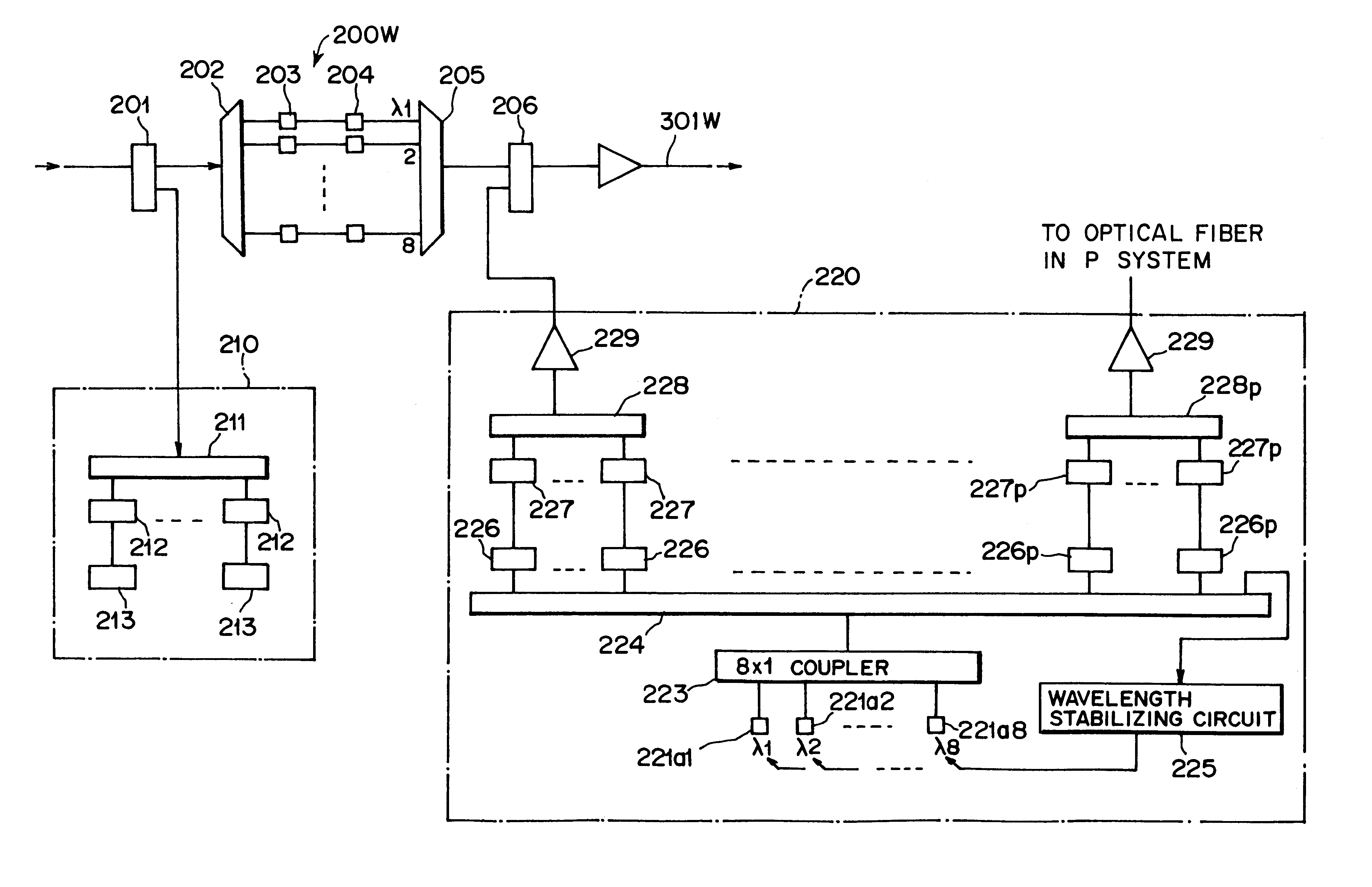
FIG. 10 is a block diagram showing a ring network 300 to which an optical ADM unit 200 according to a second embodiment of this invention is applicable. As shown in FIG. 10, the ring network 300 is made up of Ia optical fibers 301W / 301P in the W system / P system for transmitting a wavelength multiplexed signal including 8 kinds of wavelengths different from each other, and nodes 310a to 310d serving as relay stations.

The description of the same components as those in the above-mentioned optical cross connect units (b) to (b5) will be omitted for simplicity.

Each of the nodes 310a to 310d is provided with optical ADM units 200W / 200P in the W system / P system and switches 320 for conducting a switching operation between transmission paths for a wavelength multiplexed signal from the optical fiber 301W to the optical fiber 301P or vise versa.

The following description will be made of the case where each of the ADM units 200W / 200P drops lights with 5 wave...

third embodiment

(d) Description of Third Embodiment

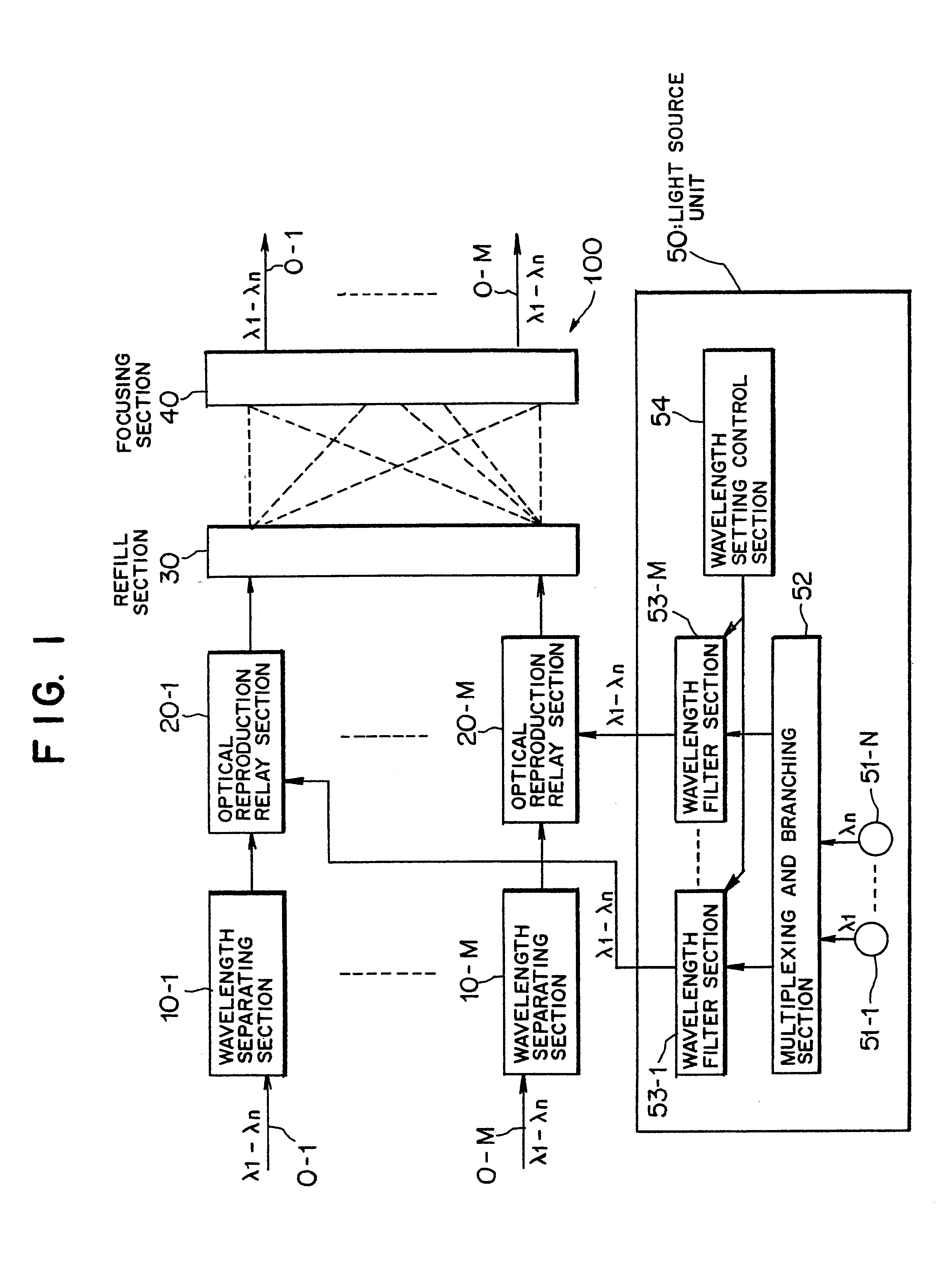
FIG. 13 is a block diagram showing a light source unit 400 according to a third embodiment of this invention. As shown in FIG. 13, the light source unit 400 is composed of N (N: natural number) LD light sources 221a1 to 221aN, a multiplexer 223, a demultiplexer 224-1 for demultiplexing a multiplexed light into N, tunable filters 226, modulators 227, an N.times.1 coupler 228-1 for multiplexing M optical signals, a wavelength stabilizing circuit 404, and an amplifier 229 for amplifying the output value of the multiplexed light.

The description of the same components as those in the above-mentioned units (b) to (c) will be omitted for simplicity.

The demultiplexer 224-1 is equivalent to the above-mentioned demultiplexer 224, while the N.times.1 coupler 228-1 corresponds to the above-mentioned 5.times.1 coupler 228 and the wavelength stabilizing circuit 404 is equivalent to the above-mentioned wavelength stabilizing circuit 55.

With this arrangement, in t...


PUM


Abstract

The present invention relates to an optical cross connect unit comprising M wavelength separating sections for receiving multiplexed optical signals each having N kinds of wavelengths different from each other through M optical fibers, respectively, and for wavelength-separating each of the multiplexed optical signals into N optical signals, M optical reproduction relay sections each for conducting an optical reproduction and relay in a manner of making a conversion of each of the N optical signals, wavelength-separated in each of the wavelength separating sections, into an electric signal and then modulating it with a desired optical wavelength, a refill section for mutually refilling M sets of optical signals optically reproduced and relayed in the optical reproduction relay sections, a focusing section for focusing the M sets of optical signals refilled in the refill section, and a light source unit for supplying input lights having desired wavelengths to be modulated in the M optical reproduction relay sections. The light source unit includes N light sources for outputting lights having the N kinds of optical wavelengths, a multiplexing and branching section for multiplexing the lights from the N light sources to produce a multiplexed light having N kinds of optical wavelength components and further for branching the multiplexed light into MxN lights to output them as multiplexed and distributed lights, M wavelength filter sections for distributively receiving N multiplexed and distributed lights of the MxN multiplexed and distributed lights branched in the multiplexing and branching section to output N lights due to the passage of only arbitrary wavelengths of the N kinds of optical wavelengths, and a wavelength setting control section for setting optical wavelengths, which pass through the wavelength filter sections, so that they differ from each other. The N lights from each of the M wavelength filter sections are supplied as the input lights. In the case that many light sources are necessary for the modulation processing by modulators or the like, this optical cross connect unit is also suitable because of using given wavelengths from a small number of light sources for a lot of modulation processing.

Description

1). Field of the InventionThe present invention relates to an optical cross connect unit, optical add-drop multiplexer, light source unit and adding unit suitably employed in the field of wavelength division multiplex transmission where a plurality of different wavelengths are multiplexed for transmission.2). Description of the Related ArtA wavelength division multiplexing (which will be referred hereinafter to as a WDM) method has been known as a transmission technique which is capable of increasing the transmission capacity and of constructing a network having flexibility in adding and dropping of signals.This WDM method relates to a technique for multiplexing and transmitting a plurality of different optical wavelength signals, and if multiplexing signals of the same transmission speed, permits the transmission of more information by a quantity corresponding to the number of wavelengths multiplexed as compared with a prior method in which light having one kind of wavelength is mo...

Claims


Application Information

Patent Timeline
IPC IPC(8): H04J14/02H04Q11/00H04M1/274G02B6/00H04B10/032H04B10/079H04B10/27H04B10/29H04J14/00H04M1/27H04M1/2746H04M1/2748H04Q3/52
CPCH04J14/0204H04J14/021H04J14/0212H04J14/0213H04J14/0217H04Q11/0005H04M1/274558H04M1/274583H04J14/0205H04M2250/60H04J14/0221H04Q2011/0016H04Q2011/0018H04Q2011/0024H04Q2011/0045H04Q2011/0049H04M1/2746H04M1/2748
Inventor OKAZAKI, KAZUEONAKA, HIROSHIMIYATA, HIDEYUKIKAI, YUTAKACHIKAMA, TERUMI
Owner FUJITSU LTD
Why Eureka
Try Eureka