Method for testing frequency response characteristics of laser displacement/vibration meters

a technology of laser displacement/vibration meter and frequency response, which is applied in the direction of instruments, using mechanical means, and analysing solids using sonic/ultrasonic/infrasonic waves. it can solve the problem of difficult to use a reference laser interferometer in an actual spot of measurement, and achieve the effect of high measurement reliability

Inactive Publication Date: 2001-09-11
DIRECTOR GENERAL OF THE AGENCY OF IND SCI & TECH
View PDF5 Cites 29 Cited by
  • Summary
  • Abstract
  • Description
  • Claims
  • Application Information

AI Technical Summary

Benefits of technology

In view of the foregoing circumstances, it is an object of the present invention to provide a method for testing frequency response characteristics of a laser displacement/vibratio...

Problems solved by technology

In the practice of the testing method just described, there may arise a situation whe...

Method used


Image

  • Method for testing frequency response characteristics of laser displacement/vibration meters
  • Method for testing frequency response characteristics of laser displacement/vibration meters
  • Method for testing frequency response characteristics of laser displacement/vibration meters

Examples


first embodiment

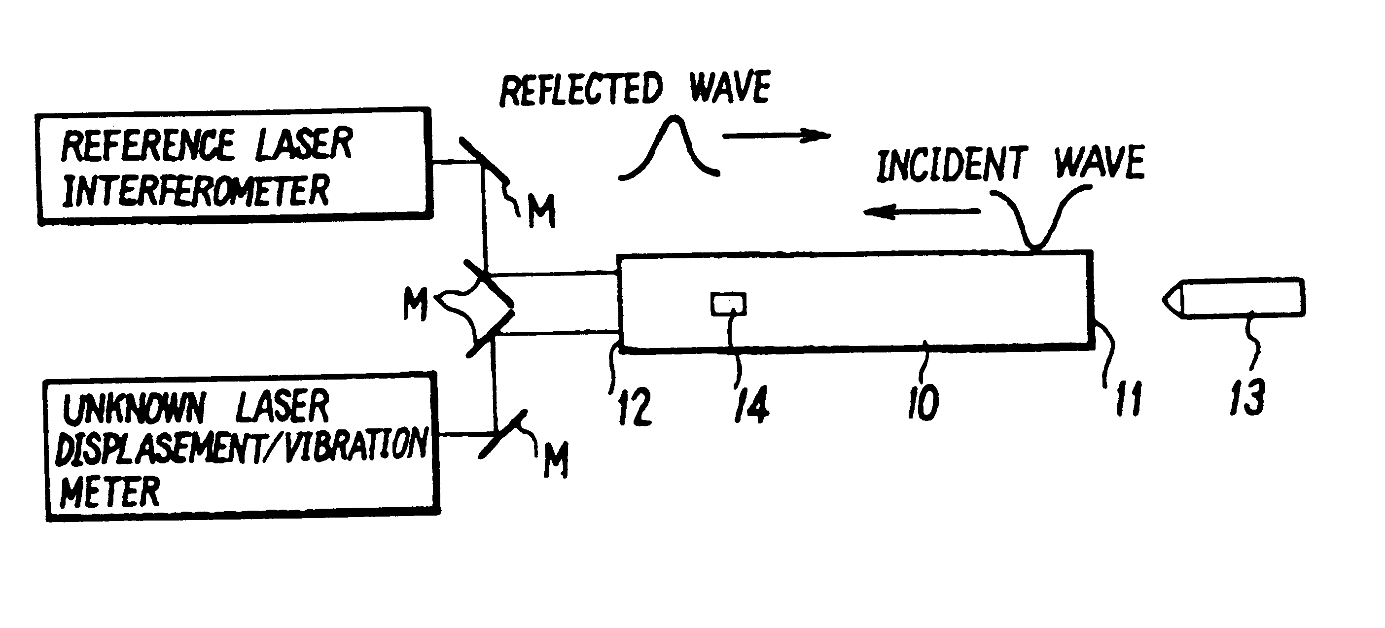
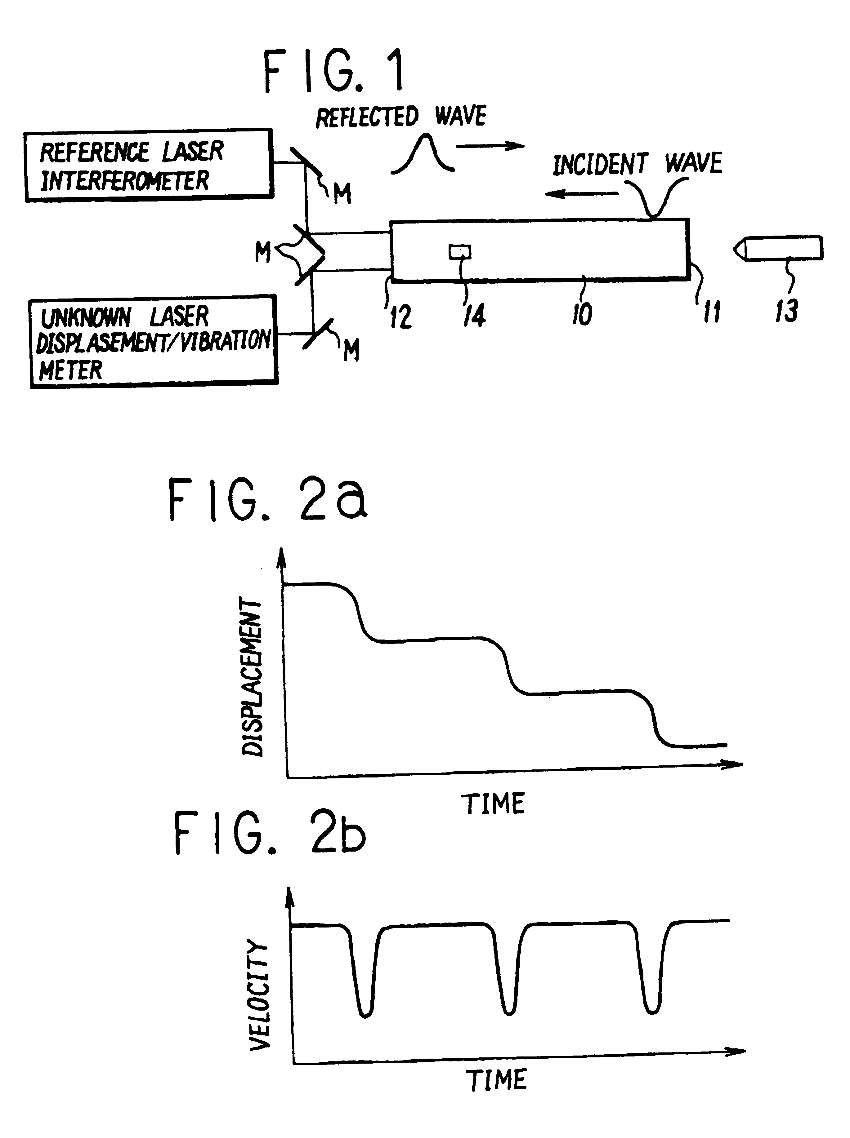
Shown in FIGS. 1 and 2 is the present invention, i.e., a method for testing frequency characteristics of a laser displacement / vibration meter.

In order to clarify the performance quality of a displacement meter or of a vibration meter with unknown frequency characteristics, it is necessary to test it by comparing its measurement data with counter measurement data produced by a reference displacement meter or vibration meter. In this connection, what is imperative to the test is how to put a surface in micro-level fine vibrational movements over a wide frequency range.

To create a vibrating surface of such nature, a round metal rod 10, which has a relatively large length as compared with its diameter as shown in FIG. 1, is employed in this particular embodiment. More specifically, for this purpose, impact is applied to one end face 11 of the round rod 10 by colliding thereagainst a flying body 13, sending forth an elastic wave pulse through the rod 10 to generate stepwise dynamic displ...

second embodiment

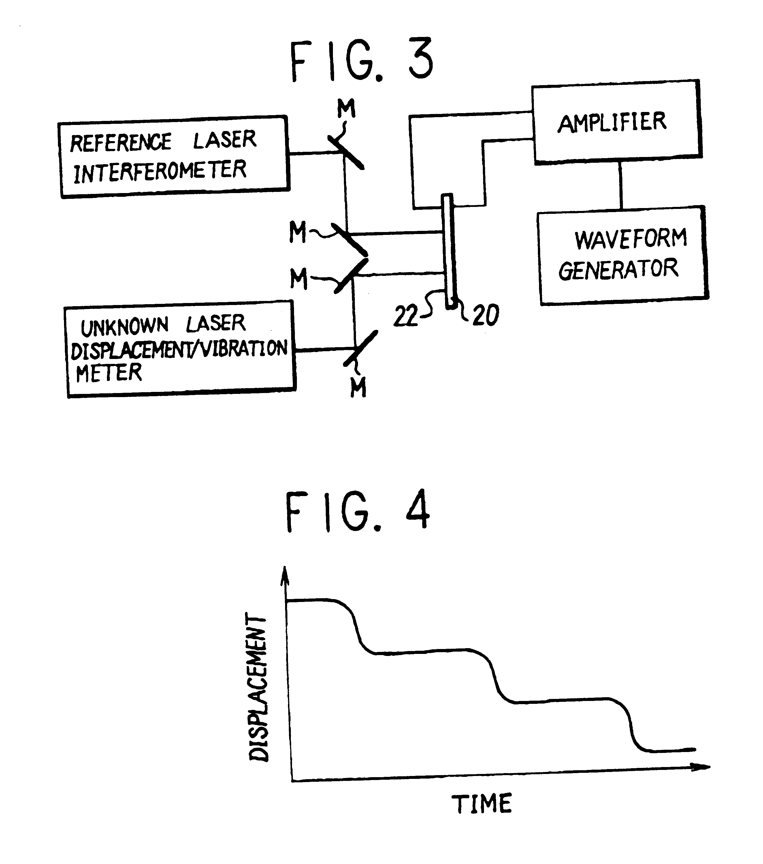
Illustrated in FIGS. 3 and 4 is the present invention which is suitable for application to measurements in higher frequency ranges.

In terms of frequency range, the first embodiment of the invention, shown in FIG. 1, can cope with from a DC component up to several hundreds kHz, but not with higher frequency ranges. In order to cover a frequency range higher than several hundreds kHz or a frequency range where the impulsive displacements or the amplitude of vibration resulting from application of an impulse voltage to a piezoelectric element can be smaller than the wavelength of the laser beam, a piezoelectric vibrator 20, which is constituted by a piezoelectric element as shown in FIG. 3, is used in place of the above-described round metal rod 10, applying thereto an impulse voltage output of a waveform generator through an amplifier to generate pulse-like dynamic displacements on a measuring surface 22 of the piezoelectric element. The above-mentioned piezoelectric vibrator 20 may b...

third embodiment

Illustrated in FIGS. 5 and 6 is the invention employing a stack of piezoelectric elements.

In measuring the velocity of movements or dynamic displacements of a surface of a piezoelectric film, there may arise situations where the frequency of measurement becomes higher and at the same time the displacement or the amplitude of vibration becomes smaller than the wavelength of the laser beam. In such a case, there may be employed a piezoelectric film 30 which is set on a stack of piezoelectric elements 31 as shown in FIG. 5. In this instance, firstly pulse-like voltage is applied to the stack of piezoelectric elements to generate a dynamic displacement of the piezoelectric film surface on which the laser beams are projected, through a parallel movement of the entire piezoelectric film with the elongation of the piezoelectric stack. In this regard, since it is easy to generate displacements larger than the wavelength of the laser bean used for the laser displacement meter, interference f...


PUM


Abstract

A method of testing frequency characteristics of a laser displacement/vibration meter by the use of a novel which can cope with a broader frequency range and finer micro-level displacements to enhance the reliability of the displacement/vibration meter. Upon applying impact on one end face of a round metal rod, an elastic wave pulse which propagates through the metal rod generates a stepwise dynamic displacement of the other end face of the rod when reflected there. This dynamic displacement is measured simultaneously by a reference laser interferometer with a reference laser beam and a laser displacement/vibration meter with unknown frequency response characteristics, followed by comparison of measurement data over a frequency range to determine the frequency response characteristics of the unknown laser displacement/vibration meter.

Description

1. Field of the ArtThis invention relates to a method for testing frequency characteristics of laser displacement / vibration meters which are widely in use in industrial fields. More particularly, this invention concerns a method for testing frequency characteristics of a laser displacement / vibration meter for the purpose of establishing traceability in the measurement of high-speed micro-level displacements and micro-level vibrations, by comparing measurement data of a laser displacement / vibration meter and a reference laser interferometer with a reference laser beam or a laser interferometer of a similar class, employing a novel technology for generating high-speed micro-level fine displacements or vibrations.2. Prior ArtLaser displacement / vibration meters have thus far been in wide use in. industrial fields for measurement of displacements and vibrations according to the principles of light-wave interference based on Doppler shifts and heterodyne light-wave interference. However, ...

Claims


Application Information

Patent Timeline
IPC IPC(8): G01N29/04G01N29/24G02F1/1335G02F1/1339G02F1/13
CPCG01N29/045G01N29/2418G02F1/13394G02F1/133514G01N2291/0421G01N2291/014
Inventor UMEDA, AKIRA
Owner DIRECTOR GENERAL OF THE AGENCY OF IND SCI & TECH
Why Eureka
Try Eureka