Accumulator and manufacturing process thereof

a technology of accumulator and manufacturing process, which is applied in the direction of manufacturing tools, brake cylinders, braking systems, etc., can solve the problems of increased weight of the overall accumulator, inability to absorb pulsation, and inability to exhibit sealing properties in the closing of valve 37

Inactive Publication Date: 2001-09-11
NHK SPRING CO LTD
View PDF4 Cites 51 Cited by
  • Summary
  • Abstract
  • Description
  • Claims
  • Application Information

AI Technical Summary

Problems solved by technology

The valve 37 may not be able to exhibit sealing properties in closing due to factors such as aging degradation thereof and jamming of foreign matter such as dust.
The end plate of the accumulator must be thick since it is slab-shaped, which results in increased weight of the overall accumulator.
However, the pressure of the pulsation occurring at a pressure lower than

Method used


Image

  • Accumulator and manufacturing process thereof
  • Accumulator and manufacturing process thereof
  • Accumulator and manufacturing process thereof

Examples


first embodiment

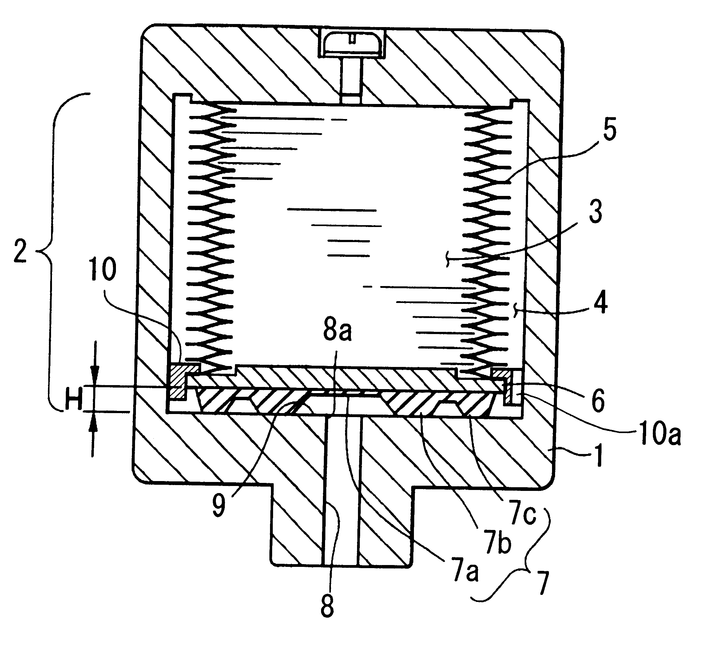
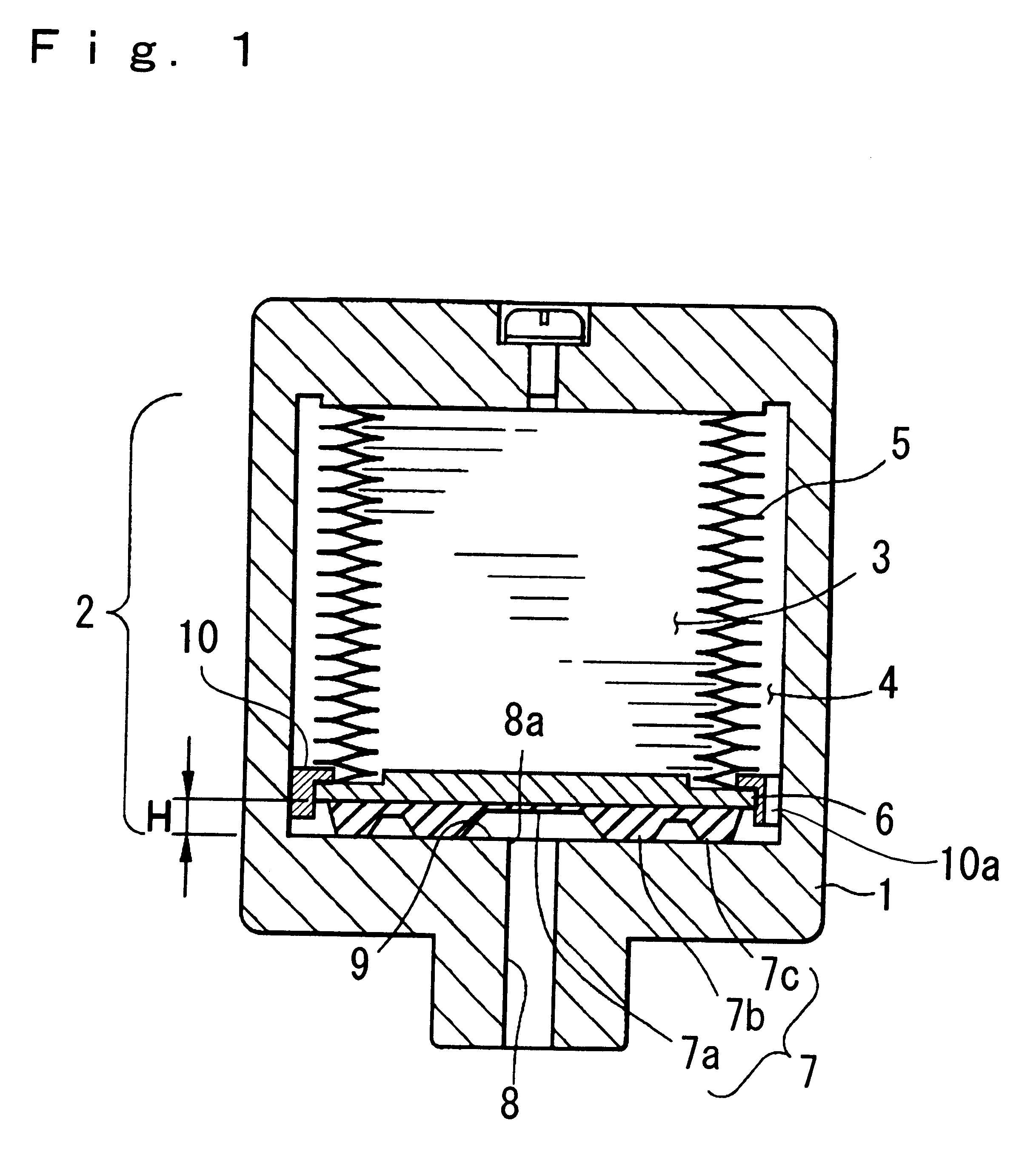
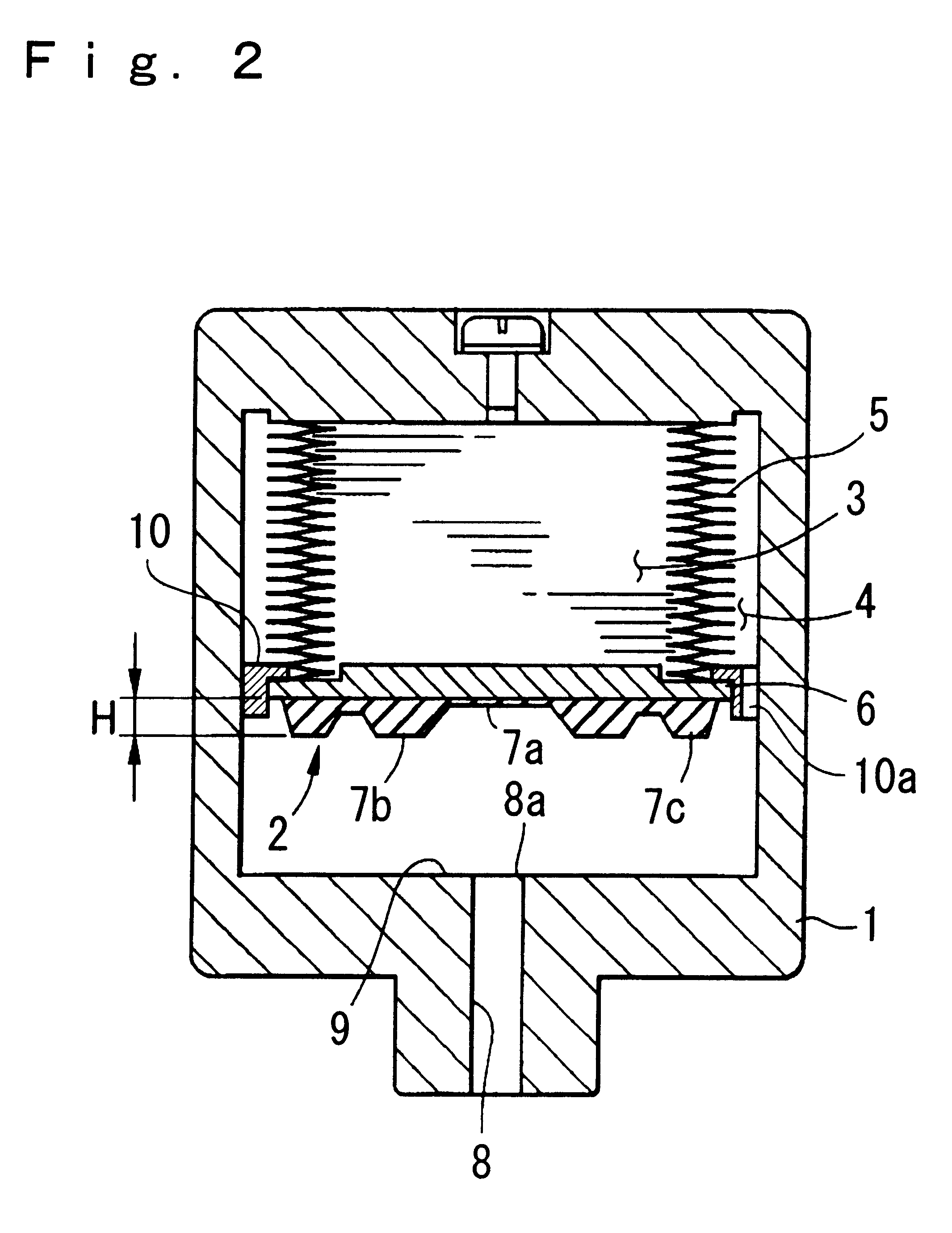
FIG. 1 shows a cross section of an accumulator according to the invention. Reference numeral 1 is a housing acting as a pressure vessel. The interior of the housing 1 is partitioned by a metallic bellows assembly 2 contained therein into a gas chamber 3 and a hydraulic chamber 4. The metallic bellows assembly 2 comprises a metallic bellows 5 having plural ribs. An end of the metallic bellows 5 is fixed to the housing 1 and the metallic bellows 5 is elastic in the axial direction of the housing 1. The assembly 2 comprises a plate 6 fixed to the free end of the metallic bellows 5 and a valve 7 fixed to the plate 6. The valve 7 is made from elastomeric materials such as rubber. A compressed gas is sealed in the gas chamber 3 in the metallic bellows 5. The hydraulic chamber 4 defined in the housing 1 and in the exterior of the metallic bellows 5 is communicated with an external system through an opening 8a and a flow path 8 formed in the housing 1.

A bellows guide 10 is fixed at the circ...

second embodiment

the invention will be explained hereinafter.

FIG. 6 is a cross section of an accumulator according to the invention, and numeral 101 is a housing acting as a pressure vessel. The housing 101 has a cylindrical shape with a bottom. The interior of the housing 101 is partitioned into a hydraulic chamber 103 and a gas chamber 104 by a metallic bellows assembly 102. The metallic bellows assembly 102 comprises a metallic bellows 105 having plural ribs and elastic in the axial direction of the housing 101, a free end cap 106 provided at the free end of the metallic bellows 105, and a base end cap 111 provided at the base end of the metallic bellows 105. The metallic bellows assembly 102 further comprises a valve 107 which is made from elastomeric materials such as rubber and is attached to the free end cap 106 at the inside of the metallic bellows 105. The metallic bellows assembly 102 is fixed to the housing 101 by fixing the base end cap 111 to the bellow-mentioned plug 108.

The hydraulic ...

third embodiment

the invention will be explained with reference to FIGS. 8 to 13 hereinafter.

FIG. 8 is a cross section showing an accumulator of the embodiment according to the invention. In the figures, reference numeral 210 is a cylindrical shell, and 240 is a metallic bellows (buffer member) which partitions the interior of the shell 210 into a hydraulic chamber 211 and a gas chamber 212. Reference numeral 250 is a port forming a communicating path in the hydraulic chamber 211 side, and 260 is a plug retainer to which a plug for sealing the gas chamber 212 is attached.

The shell 210 forms a sealed vessel by joining a bottom shell 220 as a main component and a cap shell 230 of which the axial length is shorter than that of the bottom shell 220, and the shells 220 and 230 are divided in the axial direction before the joining. The shells 220 and 230 are formed by pressing to a uniform thickness from metals such as copper, and the bodies thereof extending in the axial direction are joined to each othe...


PUM

PropertyMeasurementUnit
Pressureaaaaaaaaaa
Flow rateaaaaaaaaaa
Circumferenceaaaaaaaaaa

Abstract

Disclosed is an accumulator comprising: a pressure vessel; an elastic bellows in which a compressed gas is sealed, an end of the bellows being fixed to an interior of the pressure vessel; a flow path having an opening communicating with the interior and an exterior of the pressure vessel; a valve connected to a movable end of the bellows to operatively close the opening according to elastic motion of the bellows; and a hydraulic chamber partitioned from a gas chamber formed in an interior of the bellows containing the compressed gas. The valve comprises an upper surface which can cover the opening, and plural circular protrusions which surround the entire circumference of the opening and can closely contact the circumference of the opening.

Description

1. Field of the InventionThe present invention relates to an accumulator having a bellows, which is used for pressure accumulation or pulsation absorbing in hydraulic devices in automobile brake systems and various industrial hydraulic systems. The present invention further relates to a manufacturing process for accumulators such as the above, and more specifically relates to a joining method for shells which form a vessel for enclosing oil and gas therein.2. Background ArtFIG. 5 shows an accumulator used for hydraulic devices in automobile brake systems and various industrial hydraulic systems. The inside of a housing 31 acts as a pressure vessel and is partitioned into a gas chamber 33 in which a compressed gas is sealed therein and a hydraulic chamber 34 by a metallic bellows assembly 32. The metallic bellows assembly 32 comprises an elastic metallic bellows 35, of which one end is fixed to the housing 31 and the free end thereof is equipped with a valve 37. The hydraulic chamber...

Claims


Application Information

Patent Timeline
IPC IPC(8): F15B1/00F15B1/22F15B1/10B23K11/00B23K11/14
CPCB23K11/002F15B1/103F15B1/22B23K11/14Y10T29/49394F15B2201/205F15B2201/312F15B2201/3151F15B2201/3153F15B2201/3158F15B2201/411F15B2201/415F15B2201/60Y10T29/49893Y10T29/49877
Inventor SHIMBORI, TAKEYOSHIUMETSU, CHIHARUNAKAMURA, KOUJIMIZUKAMI, HIROSHIUENO, NAOKI
Owner NHK SPRING CO LTD
Why Eureka
Try Eureka