Collector structure having a loss ceramic member

Inactive Publication Date: 2001-09-18
NETCOMSEC
View PDF12 Cites 7 Cited by
  • Summary
  • Abstract
  • Description
  • Claims
  • Application Information

AI Technical Summary

Benefits of technology

It is therefore an object of the present invention to provide a collector of a traveling wave tube capable of maintaining vibrat

Problems solved by technology

The above-described collector structure of the conventional traveling wave tube is vulnerable to RF leakage from the collector lead line, such that, the RF power leakage occurs from the lea

Method used


Image

  • Collector structure having a loss ceramic member
  • Collector structure having a loss ceramic member
  • Collector structure having a loss ceramic member

Examples


embodiments

Referring to the drawings, preferred embodiments of the present invention will be explained in detail.

first embodiment

[First Embodiment]

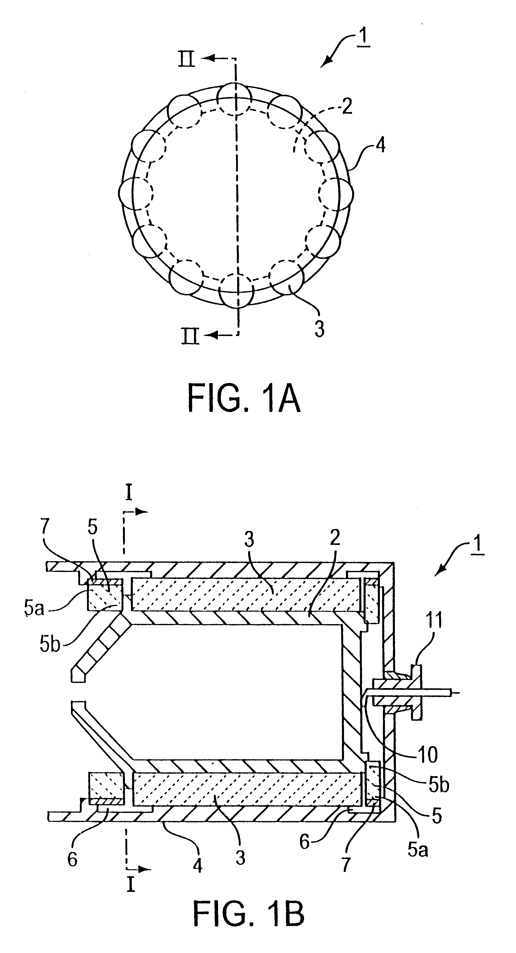
FIGS. 1(a) and 1(b) show a collector structure of a traveling wave tube (or guide) embodying the present invention. Specifically, FIG. 1a is a transverse cross-sectional view of an internal insulating type collector of a traveling wave tube and FIG. 1b is a longitudinal cross-sectional view taken along line I--I of FIG. 1a.

Referring to FIGS. 1(a) and 1(b), a collector 1 of a traveling wave tube of the present embodiment is made up of a collector electrode 2, heat conductive columnar ceramic elements 3, an outer enclosure 4 for maintaining vacuum and loss ceramic members 5 provided forwardly or rearwardly of the collector electrode 2.

The heat conductive columnar ceramic elements 3 are axially arranged (distributed) over the entire area (circumference) of an annular gap defined between the outer peripheral surface of the cylindrically-shaped collector electrode 2 and the inner peripheral surface of the cylindrically-shaped outer enclosure 4. The heat conductive colum...

second embodiment

[Second Embodiment]

As a second embodiment, an internal insulation type two-staged collector is explained.

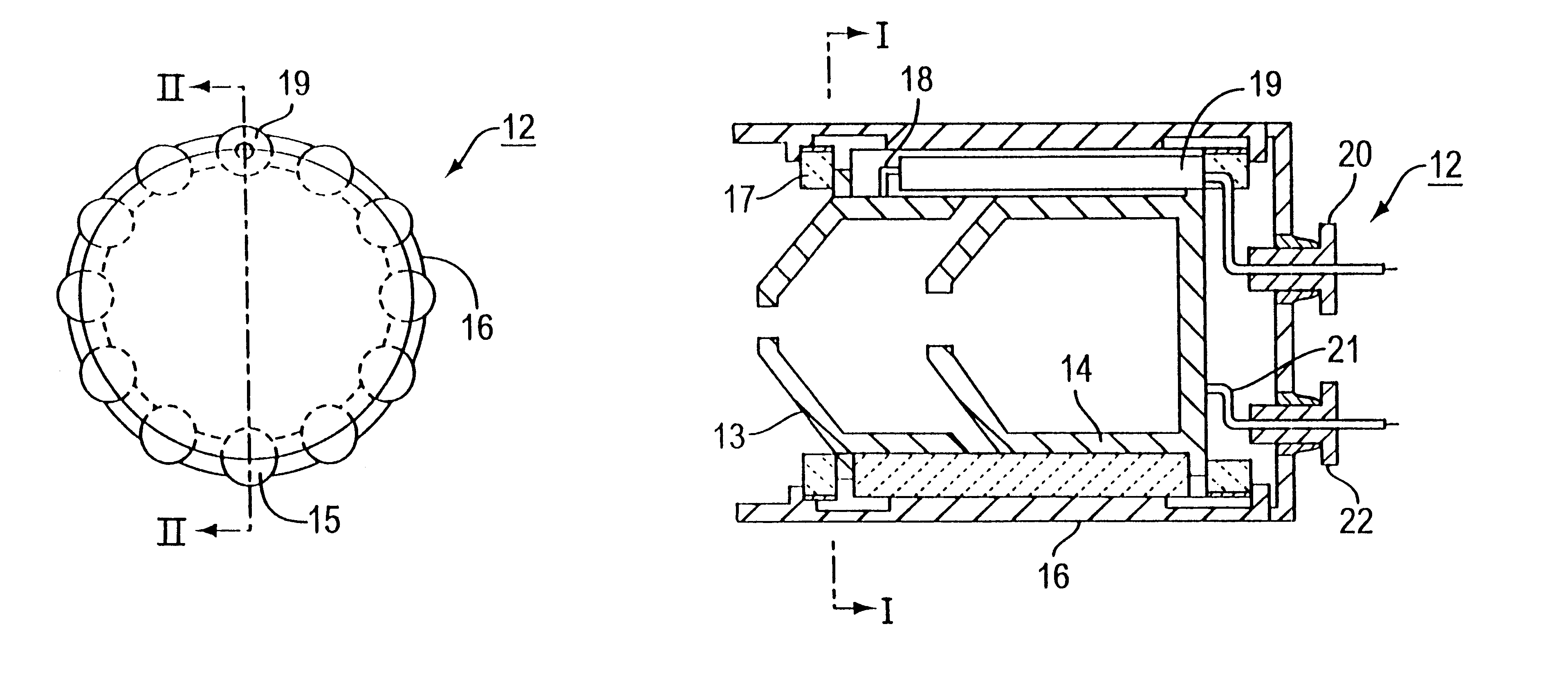
FIGS. 3(a) and 3(b) shows the collector structure 12 of the second embodiment of the present invention. Specifically, FIG. 3a is a transverse cross-sectional view of the collector structure and FIG. 3b is a longitudinal cross-sectional view taken along line II--II thereof.

Referring to FIGS. 3(a) and 3(b), the second embodiment of the present invention includes a first collector electrode 13, (see FIG. 3(b)) a second collector electrode 14 (see FIG. 3(b)), highly heat conductive columnar ceramic elements 15 (see FIG. 3(a)), an outer enclosure 16 for maintaining vacuum, loss ceramic members 17 see (FIG. 3(b)), arranged forwardly of the first collector electrode 13 and rearwardly of the second collector electrode 14, a first collector lead wire 18 (see FIG. 3(b)) extending from the first collector electrode 13 along the outer peripheral surface of the second collector electrode 14 t...


PUM


Abstract

A collector of a traveling wave tube in which a larger quantity of loss ceramic members are arranged between an outer collector enclosure and an outer surface of a collector electrode for increasing high frequency loss to prevent RF leakage from the collector lead wire. The collector includes a collector electrode 2, heat conductive columnar ceramic elements 3, an outer collector enclosure 4 for maintaining vacuum and loss ceramic members 5 arranged between the outer surface of the collector electrode 2 and the inner surface of the outer collector enclosure 4.

Description

This invention relates to a collector of a traveling wave tube.FIGS. 4 to 6 are longitudinal cross-sectional views of a conventional traveling wave tube. Specifically, FIG. 4 shows a conduction cooling type, FIG. 5 a forced air-cooling type and FIG. 6 shows a water-cooling type.FIG. 7 shows a longitudinal cross-sectional view of a conventional collector, while FIG. 8a is a transverse cross-sectional view of another illustrative structure of a conventional collector and FIG. 8b is a longitudinal cross-sectional view of FIG. 8a. FIG. 9 shows a two-stage version of the collector shown in FIG. 8. Specifically, FIGS. 9a and 9b are a transverse cross-sectional view and a longitudinal cross-sectional view of the collector, respectively.Among the devices which effect amplification of the micro-wave, using an electron beam, there is a traveling wave tube used as a relay station for micro-waves and for satellite communication.Referring to FIGS. 4 to 6, a traveling wave tube includes an electr...

Claims


Application Information

Patent Timeline
IPC IPC(8): H01J23/027H01J23/02H01J23/54H01J23/00
CPCH01J23/54H01J23/027
Inventor SUZUKI, WAKONOBE, TAKESHI
Owner NETCOMSEC
Why Eureka
Try Eureka