Underwater cable arrangements, internal devices for use in an underwater cable, and methods of connecting and internal device to a stress member of an underwater cable

Inactive Publication Date: 2001-09-18
DIGICOURSE
View PDF63 Cites 71 Cited by
  • Summary
  • Abstract
  • Description
  • Claims
  • Application Information

AI Technical Summary

Problems solved by technology

It is possible to connect such external devices with a source of power aboard the towing vessel by means of wires passing through the skin of the cable, but the necessity of forming holes in the skin for the wires can lead to leakage of water into the interior of the cable, which is highly undesirable.
However, batteries have a number of serious drawbacks.
First, the batteries have a limited life span and must be replaced every one to three months.
Not only is the replacement of the batteries time-consuming, there is also the risk of exposing electric circuitry within the external device to sea water during replacement.
In addition, lithium primary batteries, which are used because of their longer operating life compared to other batteries, are expensive, and spent batteries must be retained for proper disposal and not random

Method used


Image

  • Underwater cable arrangements, internal devices for use in an underwater cable, and methods of connecting and internal device to a stress member of an underwater cable
  • Underwater cable arrangements, internal devices for use in an underwater cable, and methods of connecting and internal device to a stress member of an underwater cable
  • Underwater cable arrangements, internal devices for use in an underwater cable, and methods of connecting and internal device to a stress member of an underwater cable

Examples


Example

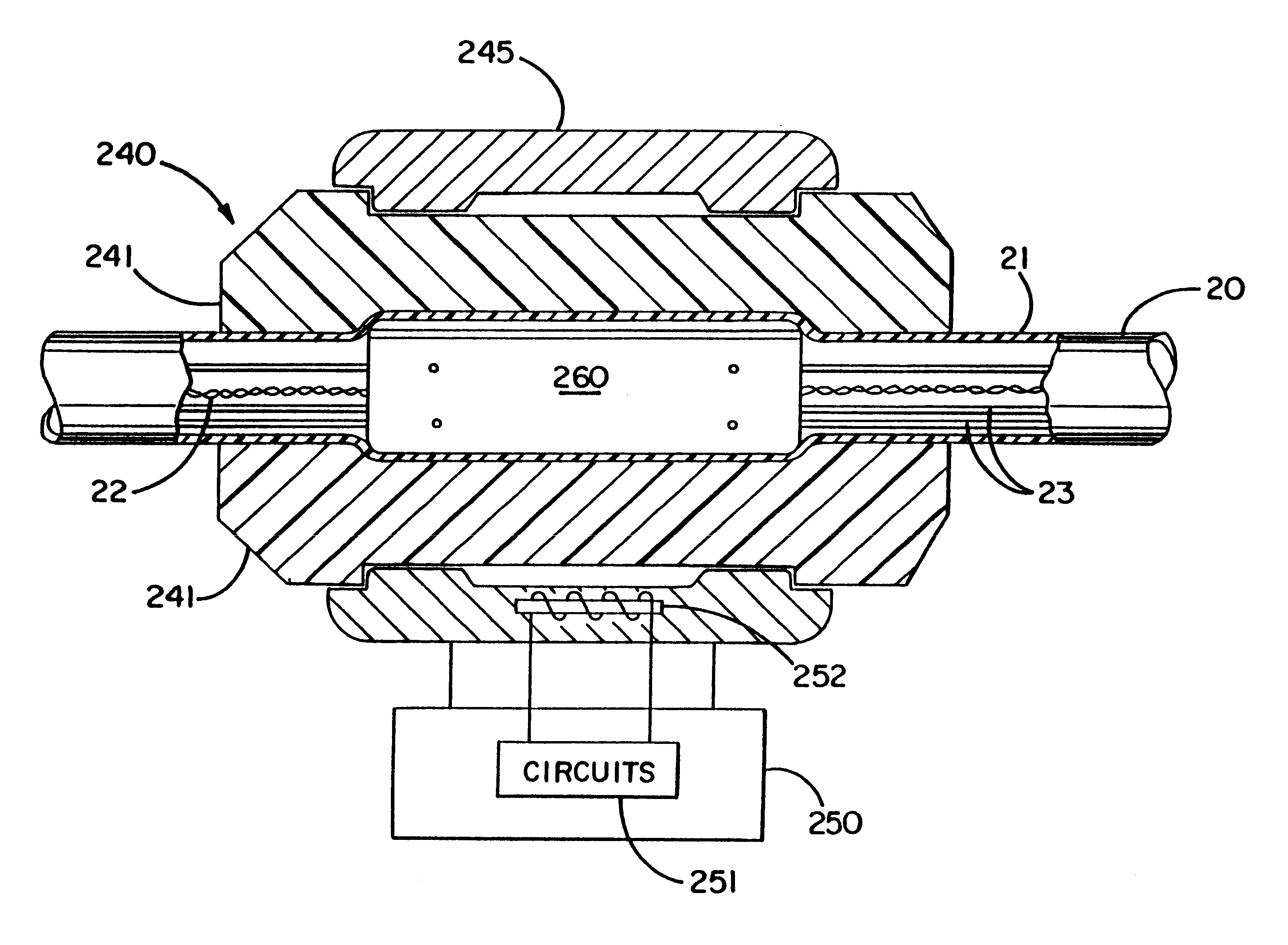
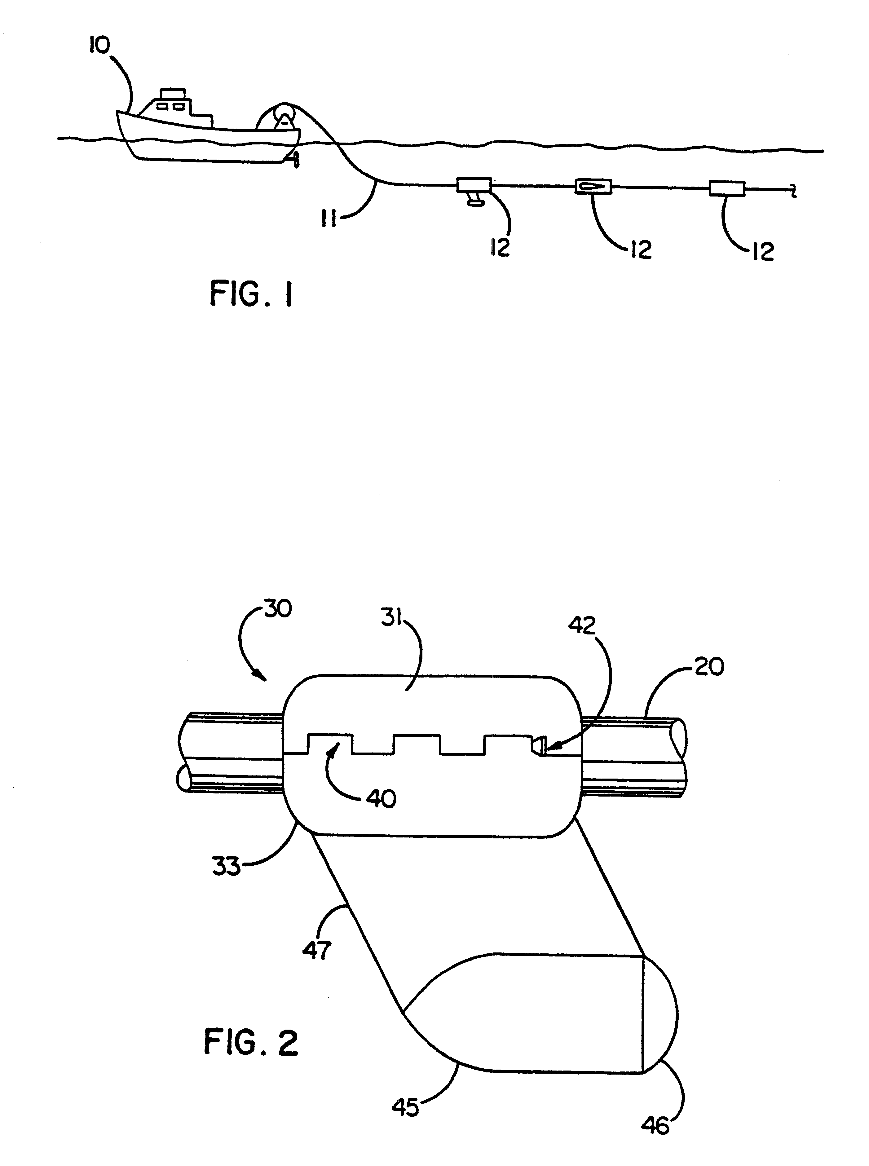
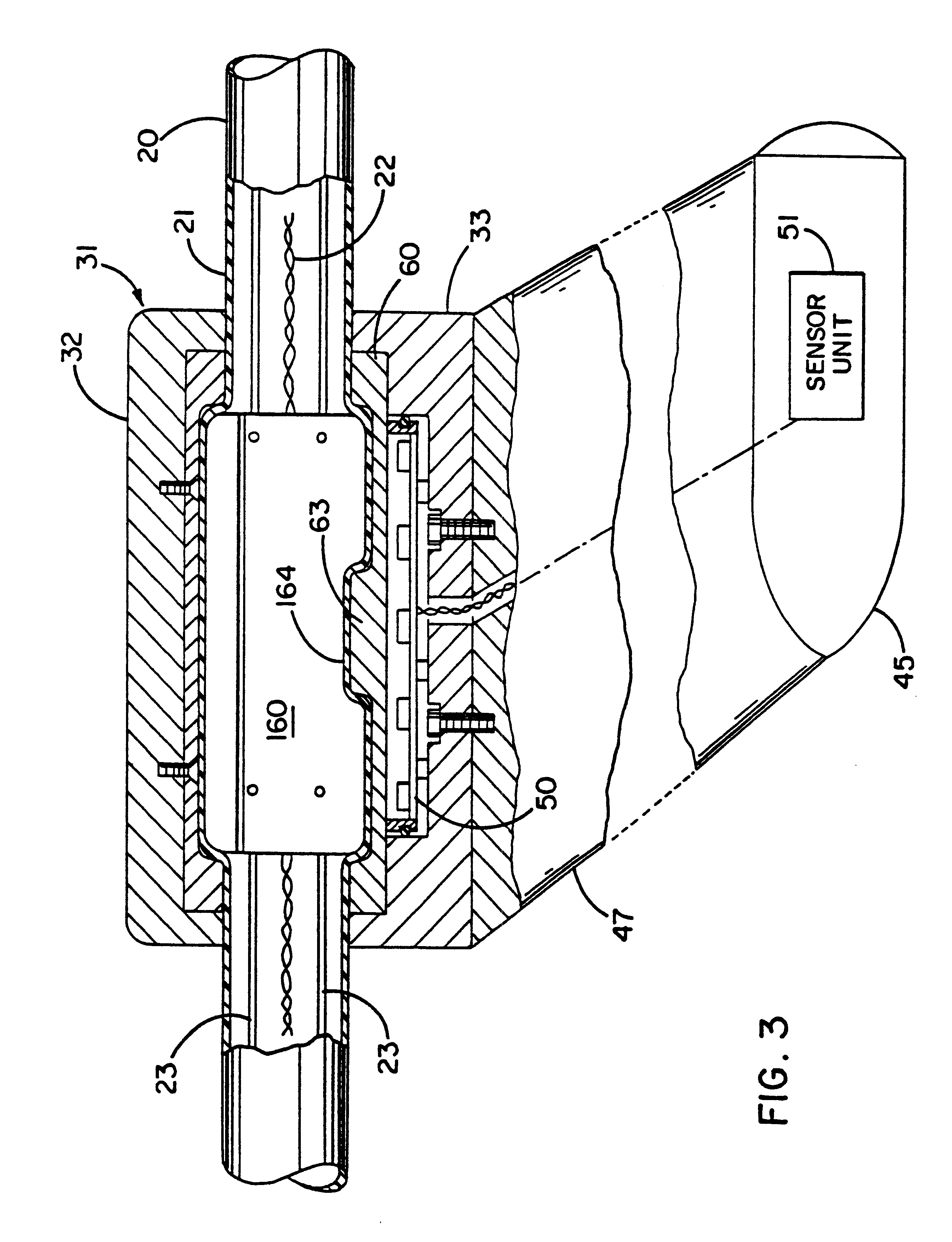
FIGS. 2 through 6 illustrate a first embodiment of an external device 30 which can be mounted on an underwater cable 20. FIGS. 2 and 3 show the external device 30 as it would appear when being towed through the water by the cable 20 to the left in the figures. The external device 30 includes a body in the form of a pod 45 for housing an electrically powered member of the external device 30, such as a sensor unit 51, a clamping portion 31 which can be releasably clamped around the cable 20 to secure the external device 30 to the cable 20, and a streamlined connecting portion 47 extending between the clamping portion 31 and the pod 45. The pod 45 is displaced from the clamping portion when it is desired to space the sensor unit 51 or other electronics in the eternal device 30 from the underwater cable 20 to reduce magnetic interference between the two. (Magnetic interference includes both electromagnetic interference and the magnetic effect of permeable materials in the cable.) Howeve...


PUM


Abstract

An internal device for use in an underwater cable may comprise a body having an outer periphery, body being mountable inside the cable with the cable surrounding the outer periphery of the body. The body may include a cutaway portion, a slot, or a dovetail joint. An underwater cable arrangement may comprise an underwater cable and an internal device disposed in the cable with the cable surrounding the device. The underwater cable may include a stress member connected to the internal device by an interference fit or the internal device may include a slot for receiving the stress member. A method of connecting a stress member of an under water cable to an internal device includes forming an interference fit between a region of increased diameter of the stress member and the internal device.

Description

REFERENCE TO RELATED APPLICATIONSThis application incorporates by reference the following applications:U.S. Provisional Application No. 60 / 004,203, filed on Sep. 22, 1995, entitled "Electrical Power Distribution and Communication System for an Underwater Cable";U.S. Provisional Application No. 60 / 004,209, filed on Sep. 22, 1995, entitled "Acoustic Ranging Device for an Underwater Cable";U.S. Provision Application No. 60 / 004,493, filed on Sep. 22, 1995, entitled "Support Device For An Underwater Cable";U.S. Provisional Application No. 60 / 004,494, filed on Sep. 22, 1995, entitled "Depth Control Device for Underwater Cables";U.S. Provisional Application No. 60 / 005,500, filed on Sep. 22, 1995, entitled "Heading Sensor Device for an Underwater Cable"; andInternational Application No. PCT / US96 / 15128, filed on Sep. 20, 1996, entitled "Electrical Power Distribution and Communication System for an Underwater Cable".1. Field of the InventionThis invention relates to an underwater cable arrang...

Claims


Application Information

Patent Timeline
IPC IPC(8): G01V1/16G01V1/20G01V1/38
CPCG01V1/3826G01V1/201
Inventor RAU, BRIEN G.OLIVIER, ANDRE' W.
Owner DIGICOURSE
Why Eureka
Try Eureka