Method for operating an electric press

a technology of electric presses and presses, applied in the field of electric presses, can solve the problems of unreliable determination of the end position only from the onset of pressing, waste of resources, and incorrect joining of workpieces

Inactive Publication Date: 2001-09-25
GEBR SCHMIDT FAB FUER FEINMECHANIK GMBH & CO KG
View PDF13 Cites 40 Cited by
  • Summary
  • Abstract
  • Description
  • Claims
  • Application Information

AI Technical Summary

Benefits of technology

In the case of the method described so far, the parameter "joining or end position" is thus dynamically adapted based on the position of the press ram at the onset of pressing, the sharp rise in compressive force upon reaching the joining position, and optionally the instantaneous value of the compressive force upon reaching the joining position; the result is greatly to reduce the effect of workpiece tolerances, so that altogether the wastage declines sharply as compared with the method known from the prior art.
The further advantage here as compared with the method described so far is that depending on how the press is used, not only the joining position but also further intermediate positions, at which the compressive force must lie within specific ranges, are monitored. What may be observed, for example, is the fact that when parts are being joined, the compressive force exhibits a certain superelevation when the press ram has travelled a certain distance since the onset of pressing and stiction transitions into sliding friction. Characteristic curve profiles of this kind can be described by parameter sets which define a "window" through which the curve for the compressive force versus displacement must pass in order for the result of the pressing operation to be satisfactory. If the curve does not pass appropriately through one of these windows, a decision can then be made relatively promptly that this pressing operation can no longer be satisfactorily completed, and it is thus terminated immediately. This early discontinuation can prevent damage to the electric press itself as well as destruction of the workpieces, which may simply have been assembled incorrectly, so that realignment of the workpieces will still allow successful joining; the result is thus once again to decrease the wastage.
The advantage here is that by processing and taking averages for several workpieces, it is possible to define reliable parameter sets or windows which are important for quality control of the pressing operation. For example, a permissible deviation in terms of compressive force or compressive displacement can be defined in the parameter sets; workpieces for which the window is missed are then picked out as waste.
The advantage here is that the profile of the compressive force can easily be observed even during the "teach-in" process, so that even at that early point corresponding windows can be defined which can then be checked or further modified when additional sample workpieces are processed. This determination of the parameter sets or windows with the greatest possible accuracy allows good control over the actual pressing operation on workpieces intended for further processing, so that their wastage can be greatly decreased.
The advantage here is that the necessary compressive force can be ascertained and defined in simple and very accurate fashion, since not only the working stroke (i.e. the displacement of the press ram) but also the compressive force applied, in particular, in the joining position, can be adjusted manually. This makes it possible to prevent the definition of an excessive compressive force which might allow the destruction of workpieces with appropriate tolerances despite the features according to the present invention described above.
In other words, it is possible by the use of an electronic handwheel to adjust the compressive force, and by way of the compressive force / displacement curves to be monitored in real time, to ascertain optimum parameter sets with the aid of sample workpieces; those parameter sets make it possible to achieve gentle and reliable joining or processing even with workpieces having coarser tolerances. The dynamic modification of these parameter sets as a function of the instantaneous compressive force profile while processing workpieces makes possible on the one hand a decrease in the wastage thanks to optimal adjustment of the compressive force and joining position, and on the other hand timely detection of failed pressing operations, as already described above.

Problems solved by technology

It has now been found that it is possible, in the context of this kind of method, for a compressive force that it is sometimes too high and also sometimes too low to be applied, depending on tolerances of the workpieces to be processed, so that some of the workpieces are not correctly joined and some are damaged by excessive compressive force.
In order to process the workpieces gently and reproducibly, they therefore must have very narrow tolerances; if these tolerances are exceeded upward or downward, the known method terminates the pressing operation because the end position is not reached and / or the compressive force is not constant; this can result in unnecessary wastage.
The joining or end position can differ for different workpieces as a function of workpiece tolerances, so that a determination of the end position solely from the onset of pressing is not as reliable as deriving the joining position from the sharp rise in the compressive force.
What is done now, in order to compensate for these tolerances, is not to predefine a high compressive force that must be reached, which is sufficient for all expected tolerances but in some cases is much too high.

Method used


Image

  • Method for operating an electric press
  • Method for operating an electric press
  • Method for operating an electric press

Examples


Embodiment Construction

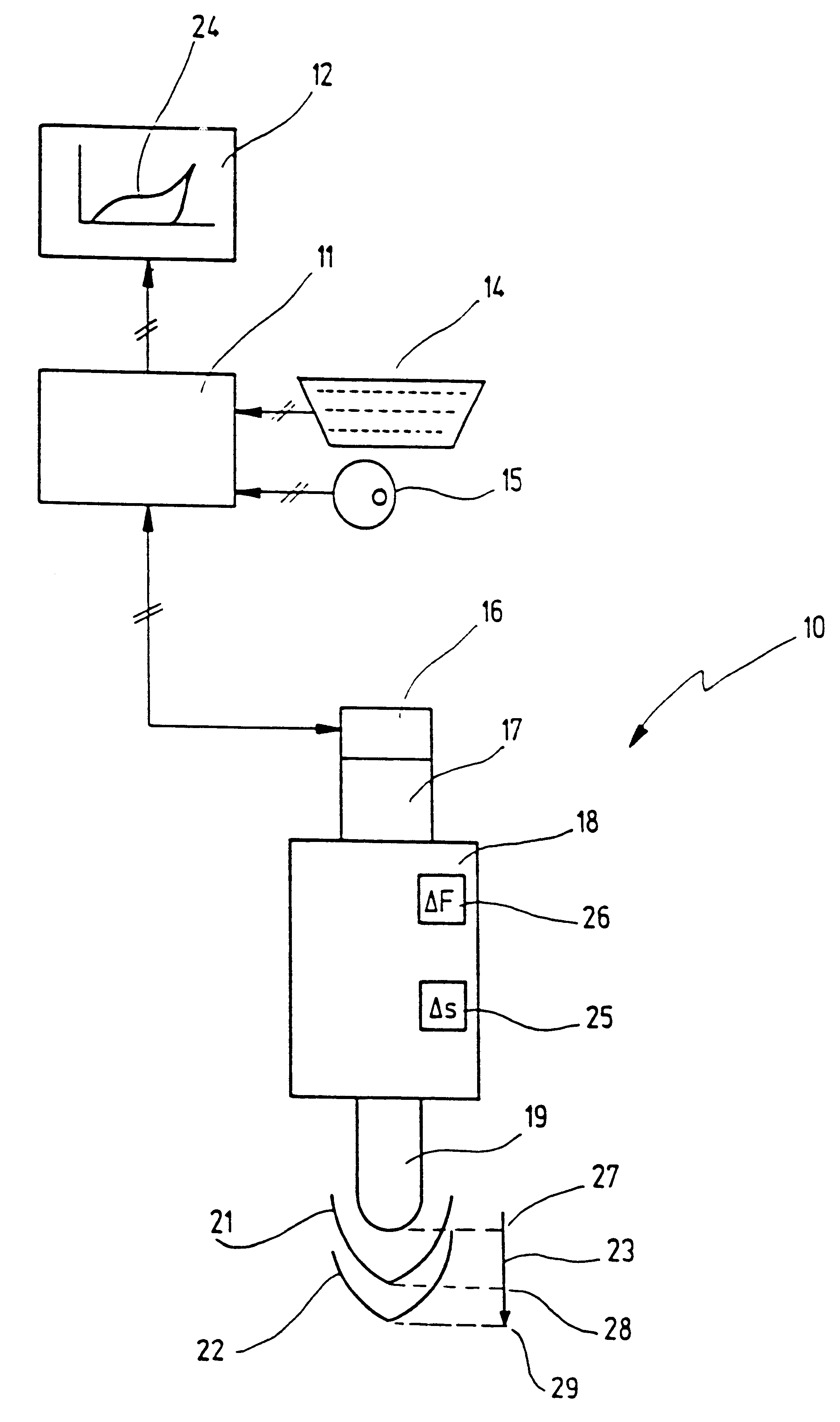
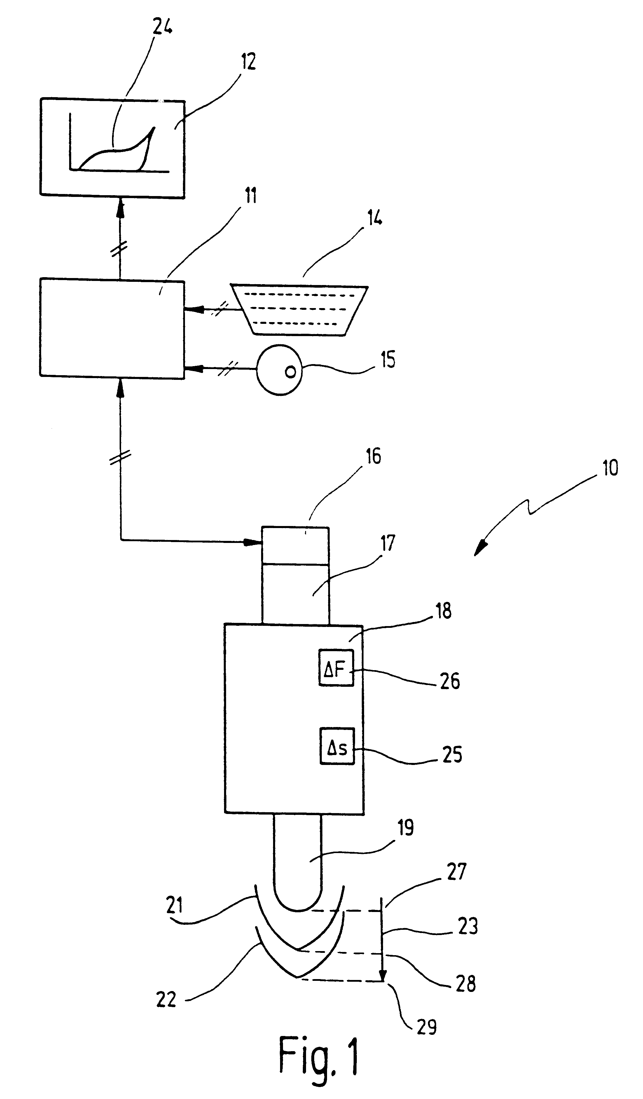
In FIG. 1, 10 generally designates an electric press which is operated via a control system indicated at 11. A screen 12, a keyboard 14, and an electronic handwheel 15 are connected to control system 11.

Also connected to control system 11 is an interface 16 of electric press 10 which makes possible control and monitoring of the pressing operations, as will be described later.

Electric press 10 has an electric motor 17 which is mounted on a housing 18. A schematically indicated press ram 19, which is actuated via electric motor 17, projects downward out of housing 18.

Schematically indicated below electric press 10 are two workpieces 21 and 22 which are to be joined to one another by electric press 10, for which purpose press ram 19 performs a working stroke indicated at 23.

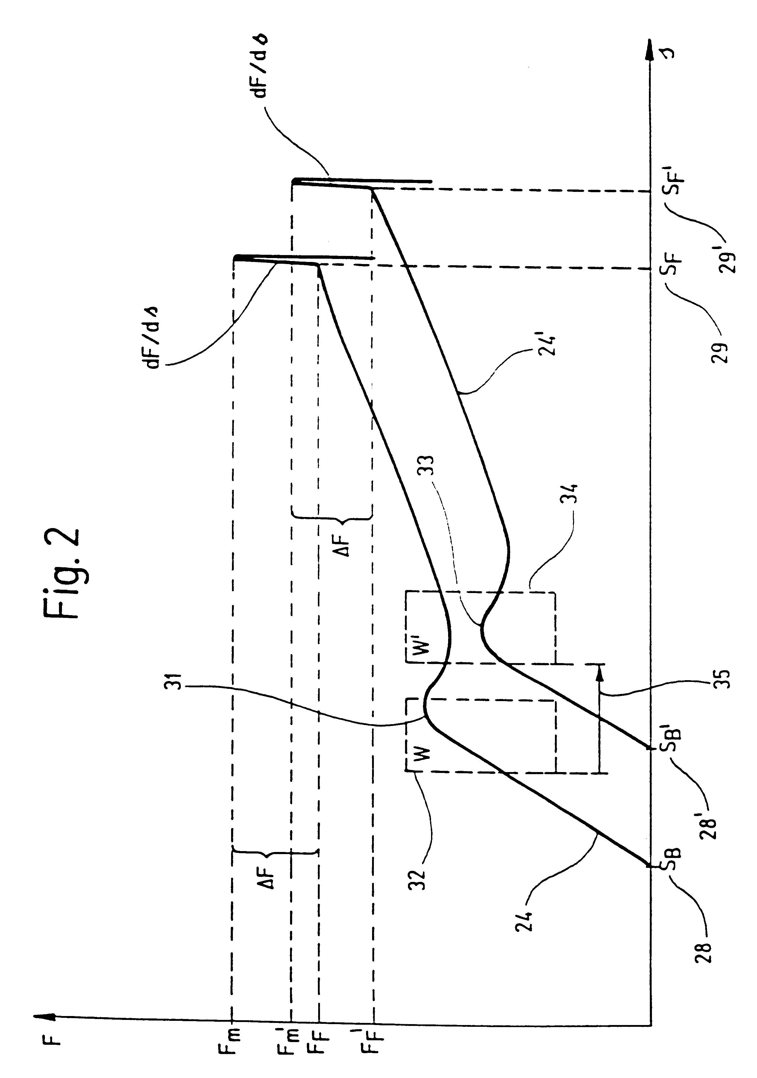
The profile for compressive force over displacement which thereby results is displayed in real time on screen 12 as curve 24, for which purpose a displacement sensor 25 and a force sensor 26 are provided in electric...


PUM

PropertyMeasurementUnit
compression forceaaaaaaaaaa
forceaaaaaaaaaa
compressive forceaaaaaaaaaa

Abstract

A method is described for operating an electric press which comprises an electrically actuated press ram, at least one displacement sensor for sensing positions of the displacement of the press ram during its working stroke, at least one force sensor for sensing compressive force applied by the press ram during the working stroke onto workpieces to be processed, and a control system which controls the working stroke in terms of displacement and compressive force. Parameters which indicate a successful course or completion of the pressing operation are dynamically adapted as a function of the profile of the compressive force versus the displacement of the press ram.

Description

1. Field of the InventionThe present invention relates to a method for operating an electric press which comprises an electrically actuated press ram, at least one displacement sensor for sensing positions of the displacement of the press ram during its working stroke, at least one force sensor for sensing compressive force applied by the press ram during the working stroke onto workpieces to be processed, and a control system which controls the working stroke in terms of displacement and compressive force, having the steps:a) moving the press ram into its initial position;b) lowering the press ram onto the workpieces to be processed, and measuring the compressive force;c) detecting the onset of pressing based on a rise in the compressive force;d) further lowering the press ram to perform the pressing operation, and monitoring the compressive force being applied; ande) halting the press ram when the latter has reached a preset joining or end position.2. Related Prior ArtA method of ...

Claims


Application Information

Patent Timeline
Patent Type & Authority Patents(United States)
IPC IPC(8): B30B15/14B30B15/00
CPCB30B15/14B30B15/0094
Inventor BABIEL, HARTMUT
Owner GEBR SCHMIDT FAB FUER FEINMECHANIK GMBH & CO KG
Why Eureka
Try Eureka