Doubly resonant push-pull flextensional

a push-pull flextensional and flex-pull technology, which is applied in the direction of electrical transducers, diaphragms of transducers, instruments, etc., can solve the problem of not being able to direct substitute these new materials for those currently used

Inactive Publication Date: 2001-10-02
THE GOVERNMENT OF THE UNITED STATES OF AMERICA AS REPRESENTED BY THE SEC OF THE NAVY NAVAL RES LAB WASHINGTON
View PDF6 Cites 26 Cited by
  • Summary
  • Abstract
  • Description
  • Claims
  • Application Information

AI Technical Summary

Problems solved by technology

However, direct substitution of these new materials for those currently used is not possible without redesigning the transducer element's mechanical and / or electrical configuration.
This is due to both elastic moduli differences and the fact that the new materials, unlike their PET counterparts, come unpolarized and require a D.C. bias for linear operation.

Method used


Image

  • Doubly resonant push-pull flextensional
  • Doubly resonant push-pull flextensional

Examples


Embodiment Construction

)

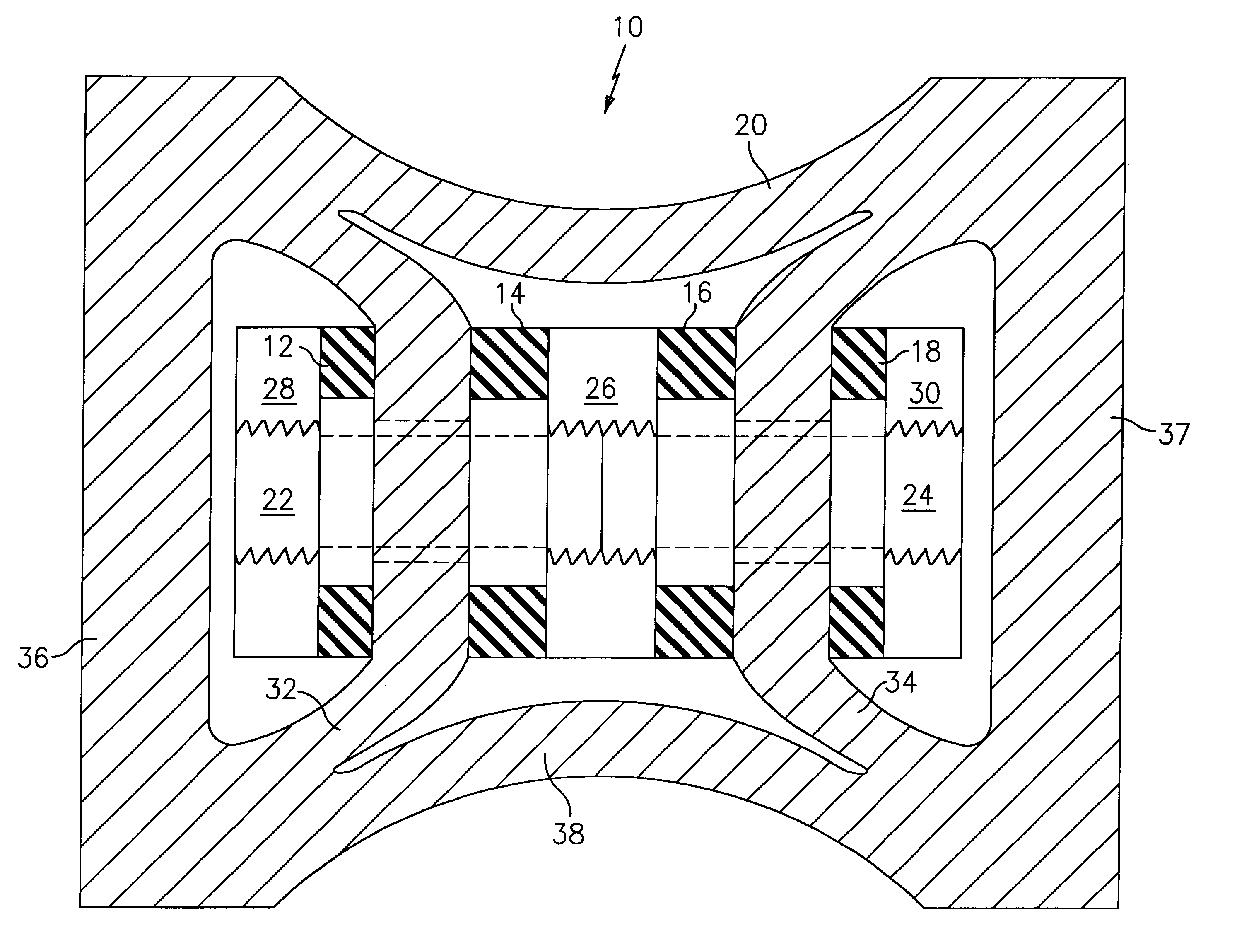
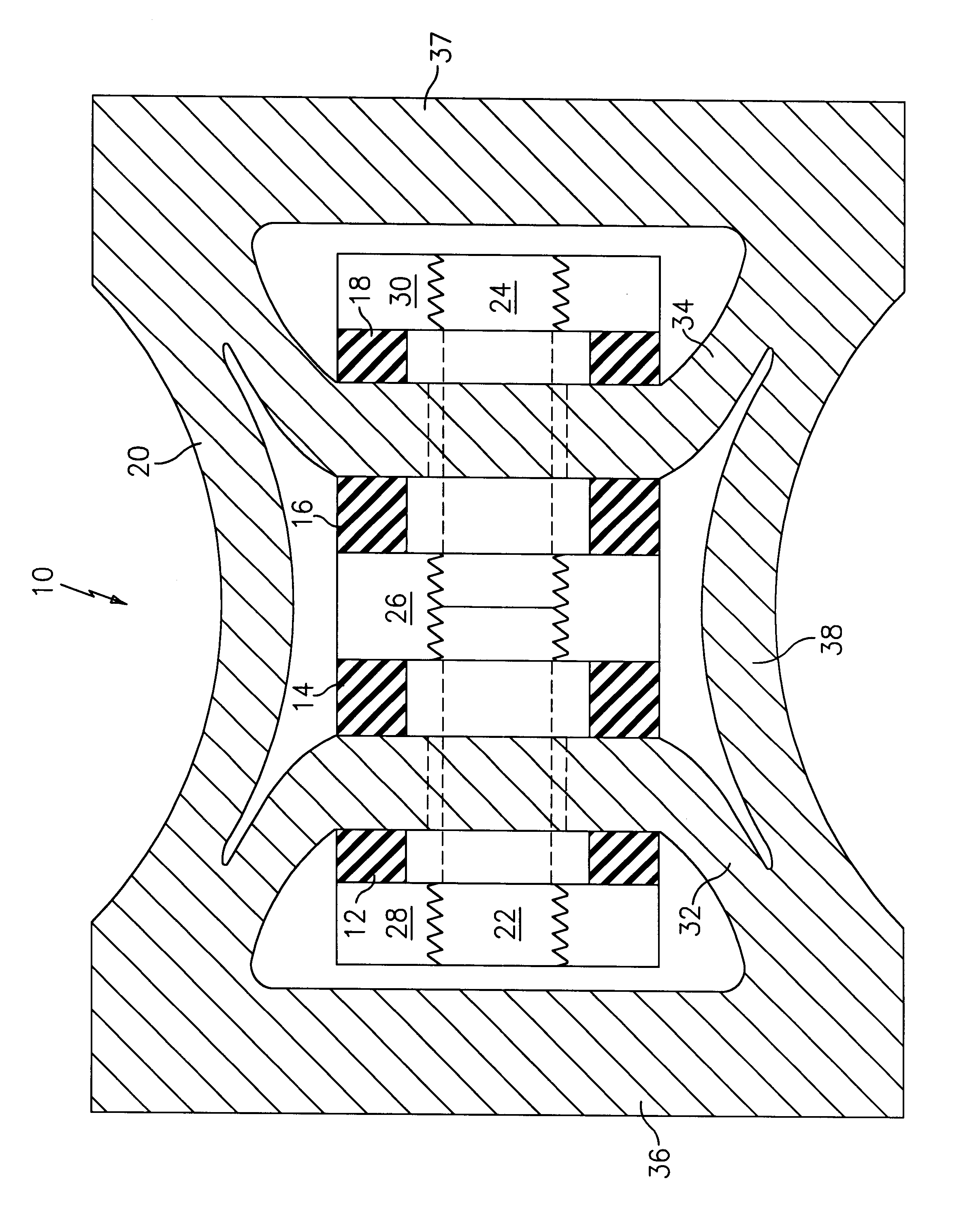
The FIGURE illustrates an improved flextensional transducer device 10 in accordance with the present invention. The transducer device 10 has a multi-resonant housing or shell 20 which flexes to propagate acoustic waves in a surrounding medium, such as seawater, and which has at least two tunable resonant modes. The shell 20 may be formed from any suitable material known in the art such as steel, glass fibers in an epoxy matrix, or an elastomeric material.

As can be seen from the FIGURE, the shell 20 has a dogbone shape. The shell 20 includes end sections 36 and 37 and a concave central section 38 joining the two end sections 36 and 37. The shell 20 further includes a pair of interior arcuately shaped web portions 32 and 34. A center web 26 is positioned within the interior of the shell 20 and may be joined to the shell 20 in any desired manner.

A plurality of rings 12, 14, 16, and 18 formed from an active drive material are positioned symmetrically about the midplane of the shell 20....


PUM


Abstract

The present invention relates to a flextensional transducer device comprising a multi-resonant shell and push-pull driving system for driving the shell so as to provide at least two tunable resonant modes, thereby increasing the operational bandwidth of the device. The push-pull driving system is formed by four rings of active drive material grouped to operate as two opposing push-pull pairs. The shell has a dog-bone configuration with two arcuately shaped interior web portions joined to the pairs of rings, end sections joined to the interior web portions, and a central concave section which functions as the primary radiating surface. Upon application of a desired current to the push-pull ring pairs, the interior web portions are caused to vibrate, which vibrations are transmitted to the end sections and the central concave section. By raising or lowering the bending stiffness of the interior web portions, the end sections, and the central concave section, one can selectively tune the modal resonance of the shell.

Description

(1) Field of the InventionThe present invention relates to a doubly resonant push-pull class IV (dog bone) flextensional transducer having an improved operational bandwidth.(2) Prior ArtFlextensional transducer devices are known in the prior art and have been used in a wide variety of applications. For example, U.S. Pat. No. 3,583,677 to Phillips describes an electro-mechanical transducer for secondary oil recovery. The transducer provides a dipole-type radiation field which extends along a single axis perpendicular to the axis of an oil well. This allows a surrounding casing to vibrate in a displacement mode rather than in a circumferential expansion mode to enable energy coupling to a surrounding oil-producing formation. The transducer includes two resonant beams forced to vibrate at an audio or sonic frequency by piezoelectric element stacks driven by an external electrical power source and transferring energy through additive shear waves to an external body. The transducer descr...

Claims


Application Information

Patent Timeline
Patent Type & Authority Patents(United States)
IPC IPC(8): G10K9/12G10K9/00H04R7/00H04R7/04
CPCG10K9/121H04R7/045
Inventor BENJAMIN, KIM C.
Owner THE GOVERNMENT OF THE UNITED STATES OF AMERICA AS REPRESENTED BY THE SEC OF THE NAVY NAVAL RES LAB WASHINGTON
Why Eureka
Try Eureka