Object oriented software build framework mechanism

a software and framework technology, applied in the field of data processing systems, can solve the problems of wasting resources, oo technology is significantly different, and no structured build processor is sufficiently flexible and adaptable, and achieves the effect of being ready to customiz

Inactive Publication Date: 2001-10-02
IBM CORP
View PDF31 Cites 99 Cited by
  • Summary
  • Abstract
  • Description
  • Claims
  • Application Information

AI Technical Summary

Benefits of technology

It is important to note, though, that the common interface of a pure virtual operation definition must be honored by all subclasses such that requesting objects (called client objects) can use subclass member objects (called server objects) without needing to know the particular subclass of the server object. For example, whenever the object defined by the zoo administrator class needs a particular action performed, it interacts with a zoo keeper object. Because the interface to these objects was defined in abstract, base class zoo keeper and preserved in the subclass definitions for the check_animals( ) operation, the zoo administrator object need not have special knowledge about the subclasses of any of the server objects. This has the effect of decoupling the need for the action (i.e., on th...

Problems solved by technology

There presently is no structured build processor that is sufficiently flexible and adaptable to permit re-use across different system installations and platforms.
This wastes resources.
Stated another way, OO technology is significantly different from procedural technology because problems are broken down into sets of cooperating objects instead of into hierarchies of nested computer programs or procedures.
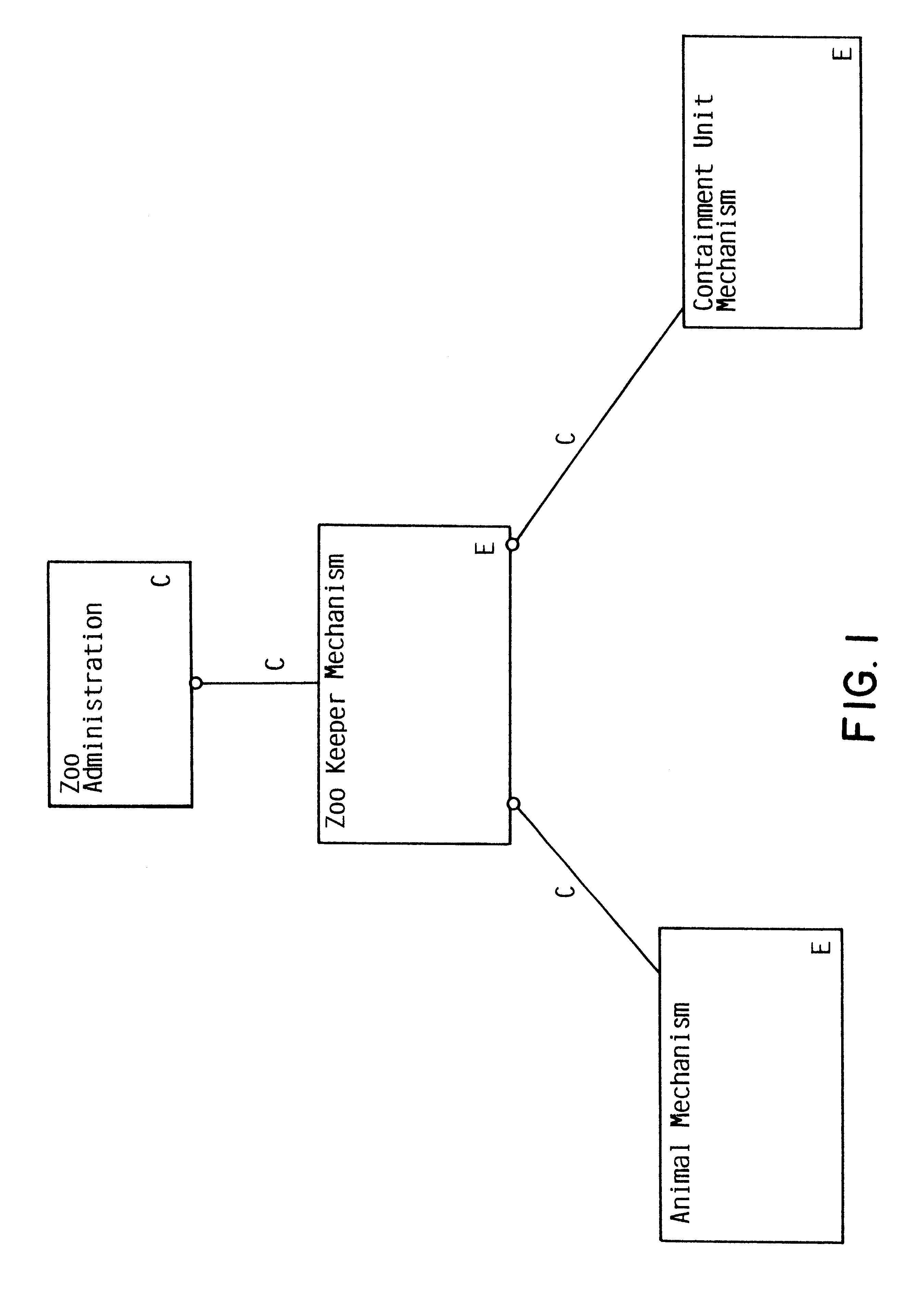
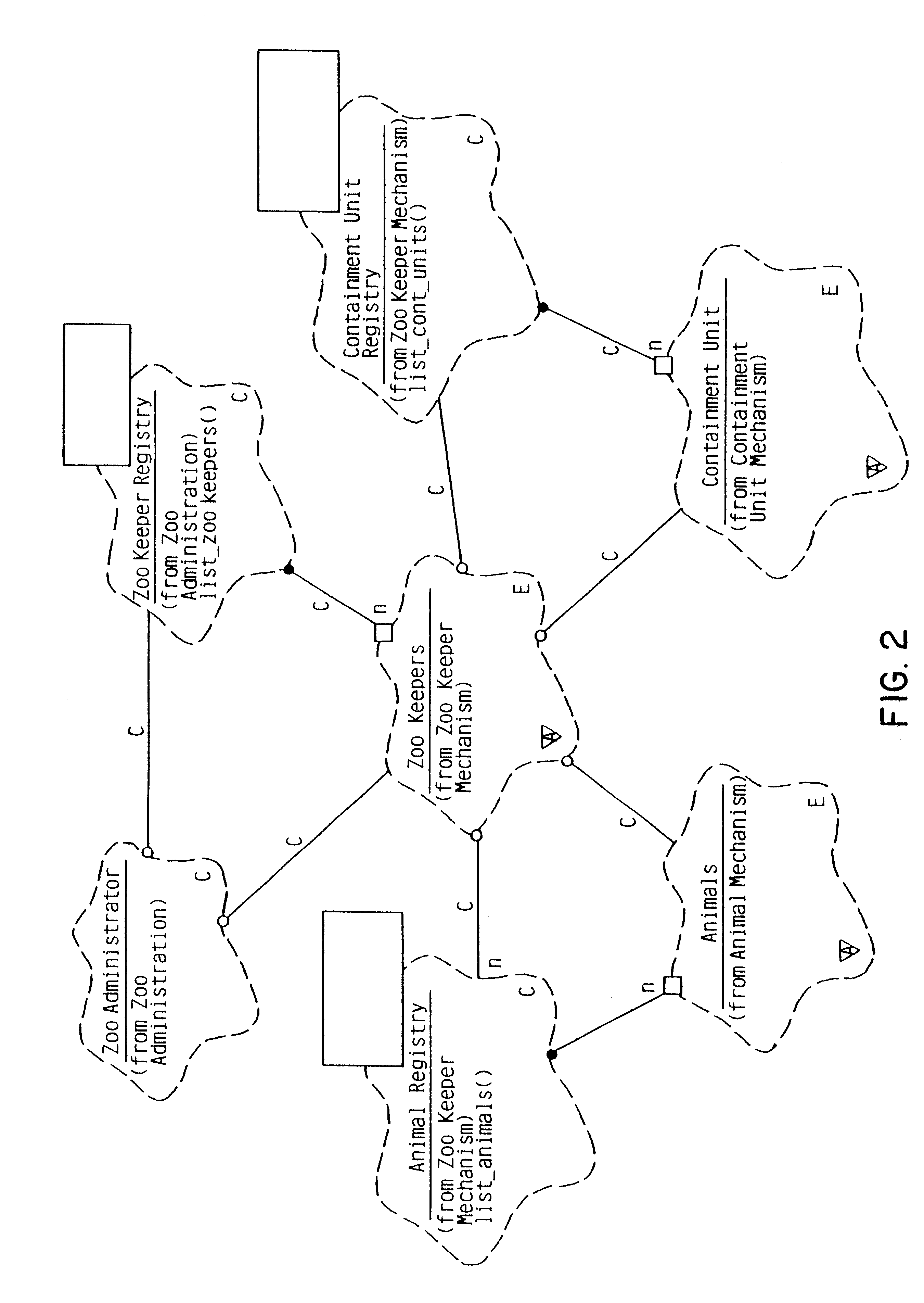
The specific problem presented is that of designing a framework that assists zoo keepers in the care and feeding of zoo animals.
Note further that the "uses" relationship between the zoo administration mechanism and the zoo keeper mechanism also has been designed as a core function such that it is not available for ultimate customization by the framework co...

Method used


Image

  • Object oriented software build framework mechanism
  • Object oriented software build framework mechanism
  • Object oriented software build framework mechanism

Examples


Embodiment Construction

FIG. 8 is a block diagram of a computer system 30 constructed in accordance with the present invention. The computer system includes a central processing unit (CPU) 32 that operates in response to operator commands, which it receives from an operator / display interface 34 to which it is connected by a system bus 36. The CPU also communicates over the system bus with a main memory 38. The main memory is illustrated containing a variety of data structures, including application programs 40, objects 42, data 44, and an operating system 46. The main memory 38 is represented as a single entity, but those skilled in the art will appreciate that the main memory can comprise a combination of random access memory (RAM), hard disk drives, optical disk drives, and other storage devices containing logically segmented storage locations.

The operating system 46 preferably supports an object oriented programming environment such as provided, for example, by the C++ programming language. The applicat...


PUM


Abstract

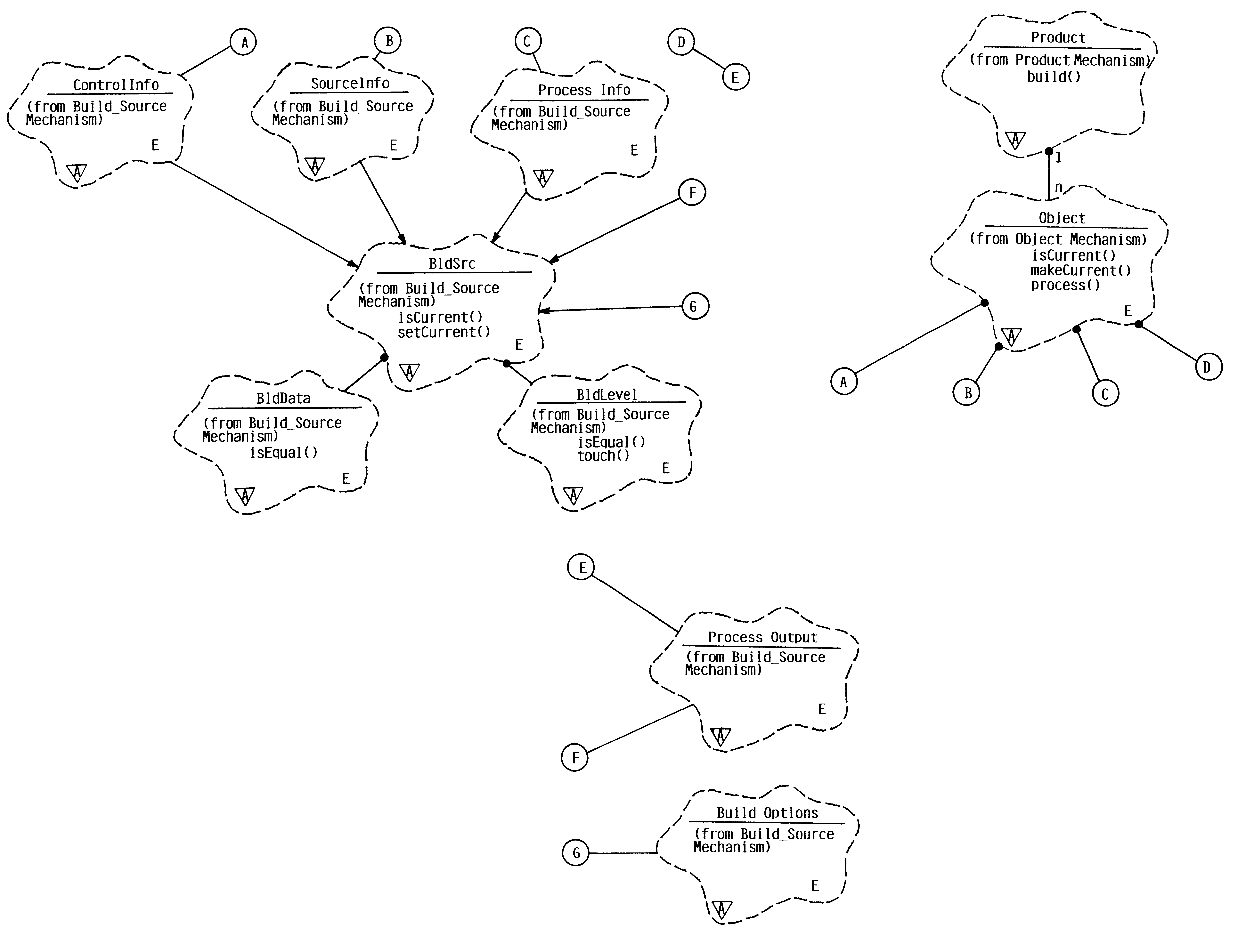
A framework for use with object-oriented programming systems provides a software build system that detects modules that make up a software product, examines each module to determine if it is up-to-date, and automatically updates any modules that require processing. The framework includes a software object of a class called "Product" that comprises a software product to be processed and built. An instance of the Product is comprised of multiple software build objects, each of which is called "Object". Each Object in turn contains four objects that are a kind of object class called BldSrc (Build Source). The BldSrc objects specify a different aspect of the software product and desired processing. Each of the software build objects in a Product's Object list is examined to determine if all four of the BldSrc objects is current. If any one of the software build objects is not current, the Object is re-built. If all four objects are current, the re-building step is skipped. In this way, each of the software build Objects making up a Product is automatically examined and processed, and the Product is produced.

Description

1. Field of the InventionThe present invention relates generally to data processing systems and, more specifically, to object-oriented programming systems and processes.2. Description of the Related ArtSoftware development requires writing source code comprising lines of computer programming written in a suitable programming language and assembling executable code generated from the source code into a software product that can be loaded into computer memory and executed. The step of assembling executable code is referred to as a software build process. As part of the software build process, source input comprising source code and control information is processed by a compiler or similar utility control program. The compiled or otherwise processed code comprises executable control program output data. The executable output data can then be loaded onto a system and accessed by system users so the underlying application can be used.There are many situations for which it might be necess...

Claims


Application Information

Patent Timeline
IPC IPC(8): G06F9/44
CPCG06F8/71
Inventor MISHESKI, DAVID JOSEPHNOCK, CLIFTON MALCOLM
Owner IBM CORP
Why Eureka
Try Eureka