Reverse osmosis filtering apparatus with concentrate dilution

a reverse osmosis and filtering technology, applied in the direction of piston pumps, multi-stage water/sewage treatment, separation processes, etc., can solve the problems of high operating costs and inefficiencies in the system, inefficient arrangement, and inability to filter effectively, etc., to achieve high efficiency, less energy, and high filtering

Inactive Publication Date: 2001-10-09
PERMAR CLARK
View PDF11 Cites 82 Cited by
  • Summary
  • Abstract
  • Description
  • Claims
  • Application Information

AI Technical Summary

Benefits of technology

The apparatus of the present invention, in common with some of the prior art patents noted above, is for the purpose of filtering liquid, such as sea water when the liquid is pressurized. However, the present invention is characterized by its ability to provide highly effective filtering with the expenditure of considerably less energy than the systems known in the prior art. As

Problems solved by technology

It is known to pump sea water or other liquid seriatim through a series of reverse osmosis filters, however, such arrangements are inefficient in that downstream filters tend to cl

Method used


Image

  • Reverse osmosis filtering apparatus with concentrate dilution
  • Reverse osmosis filtering apparatus with concentrate dilution
  • Reverse osmosis filtering apparatus with concentrate dilution

Examples


Embodiment Construction

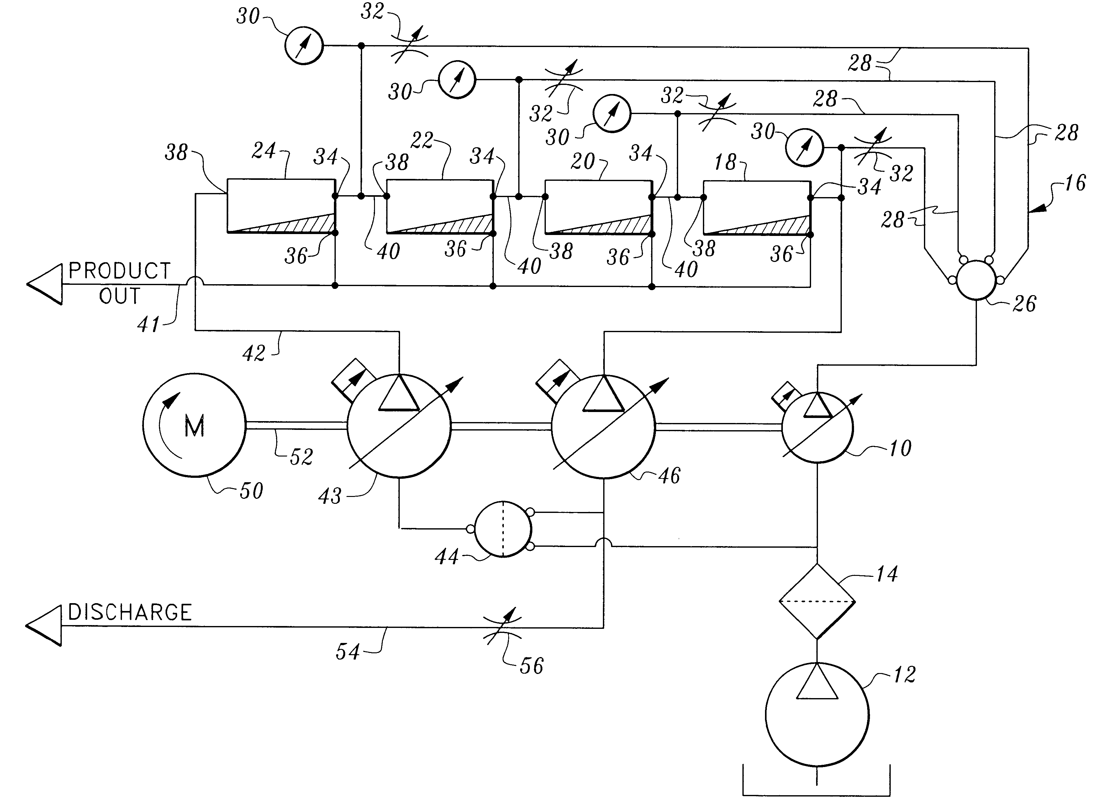
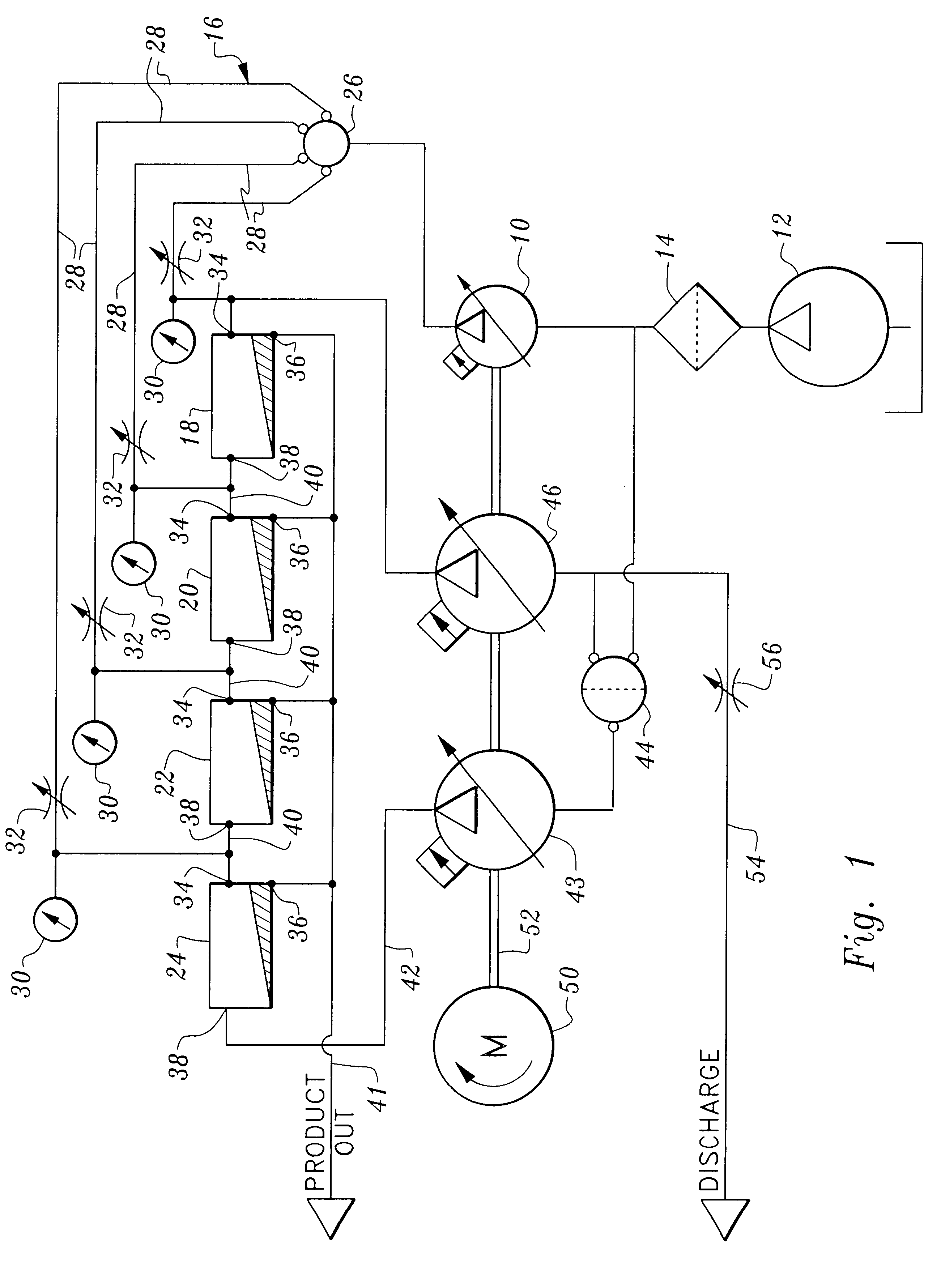
Referring now to FIG. 1, one embodiment of my invention includes a liquid pump 10 which receives a liquid, such as seawater, from a feed boost pump 12, the liquid passing through a filter 14 before being received by liquid pump 10. The disclosed liquid pump 10 is a variable displacement pressure compensated injection feed pump and is utilized to pressurize liquid received from feed boost pump 12 to a much higher pressure, e.g. from about 30 psi to about 800 psi. Liquid pump 10 could be a fixed displacement pump controlled by an adjustable speed drive.

Liquid flow path defining means 16 is connected to liquid pump 10 and distributes liquid under pressure separately to each of a plurality of reverse osmosis filters 18, 20, 22, 24. The liquid flow path defining means 16 includes a plenum 26 and four liquid delivery conduits 28, each of the latter leading a reverse osmosis filter. A pressure gauge 30 is operatively associated with each of the liquid delivery conduits to indicate the pres...


PUM

PropertyMeasurementUnit
Pressureaaaaaaaaaa
Flow rateaaaaaaaaaa
Sizeaaaaaaaaaa

Abstract

Liquid filtering apparatus includes a plurality of reverse osmosis filters for receiving seriatim under pressure a mixture of feed liquid and recirculated concentrate. Feed liquid such as salt water is introduced into the inlet of each reverse osmosis filter to dilute the recirculated concentrate.

Description

This invention relates to apparatus for providing a flow of pressurized liquid and passing the pressurized liquid through a plurality of reverse osmosis filters to separate the pressurized liquid into a permeate portion and a concentrate portion. The apparatus is particularly useful for desalinization of seawater.My U.S. Pat. No. 5,482,441, issued Jan. 9, 1996, discloses a system which can be utilized to desalinate seawater. The system includes a rotary variable displacement liquid pump and rotary metering device driven by a drive motor to pump liquid through containment structure and a single reverse osmosis filter.My U.S. Pat. No. 5,462,414, issued Oct. 31, 1995 and U.S. Pat. No. 5,628,198, issued May 13, 1997, disclose other approaches to solving certain problems inherent in the prior art and have features in common, including the use of a reversible piston which cooperates with filter means to produce desalinated water.U.S. Pat. No. 4,793,153, issued Dec. 27, 1998, discloses a p...

Claims


Application Information

Patent Timeline
IPC IPC(8): B01D61/10B01D61/06B01D61/02F04B9/115F04B9/00F04B23/06F04B23/00C02F1/44
CPCB01D61/022B01D61/06B01D61/10F04B9/115F04B23/06C02F1/441B01D61/026
Inventor PERMAR, CLARK
Owner PERMAR CLARK
Why Eureka
Try Eureka