Component for optical data transmission

a technology of optical data transmission and components, applied in the direction of transmission, transmission monitoring/testing/fault-measurement systems, transmission, etc., can solve the problems of reducing the sensitivity of the receiver, high material costs, and large dimensions of the transceiver, and achieve high transmission power and high receiver sensitivity

Inactive Publication Date: 2001-10-09
VISHAY SEMICON
View PDF9 Cites 50 Cited by
  • Summary
  • Abstract
  • Description
  • Claims
  • Application Information

AI Technical Summary

Benefits of technology

is to provide a component which in spite of smaller dimensions pr

Problems solved by technology

Conventional transceivers have the disadvantage that due to the transmitter and the receiver being located adjacent to each other, they each require their own respective optical system in order to be able to achieve the required directional signal transmission of the transmitter and the directional sensitivity of the receiver.
This duplication causes high material costs and the dimensions of the transceiver are relatively large.
If the integrated circuit, the receiver, and the transmitter are arranged in a stack, that

Method used


Image

  • Component for optical data transmission
  • Component for optical data transmission
  • Component for optical data transmission

Examples


Embodiment Construction

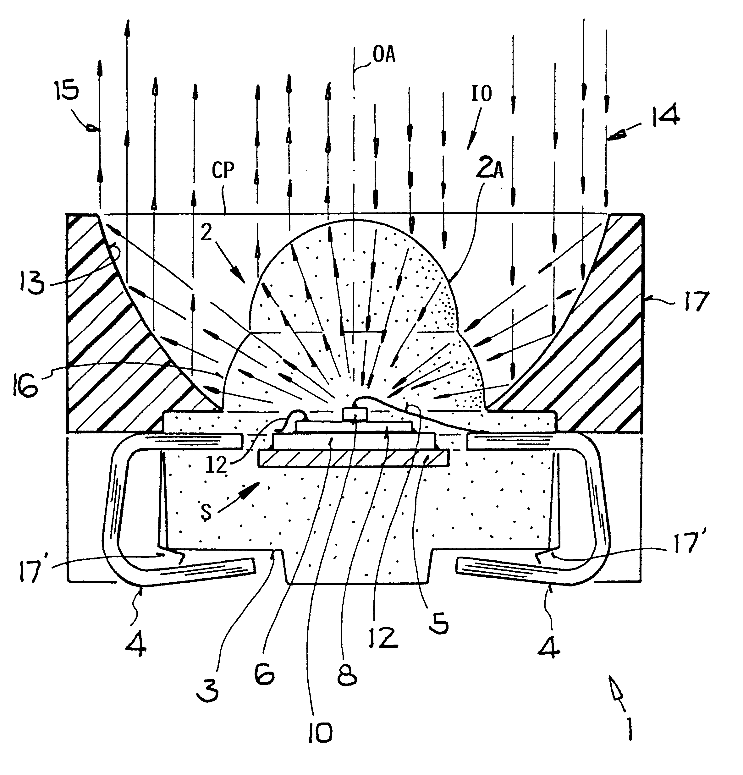
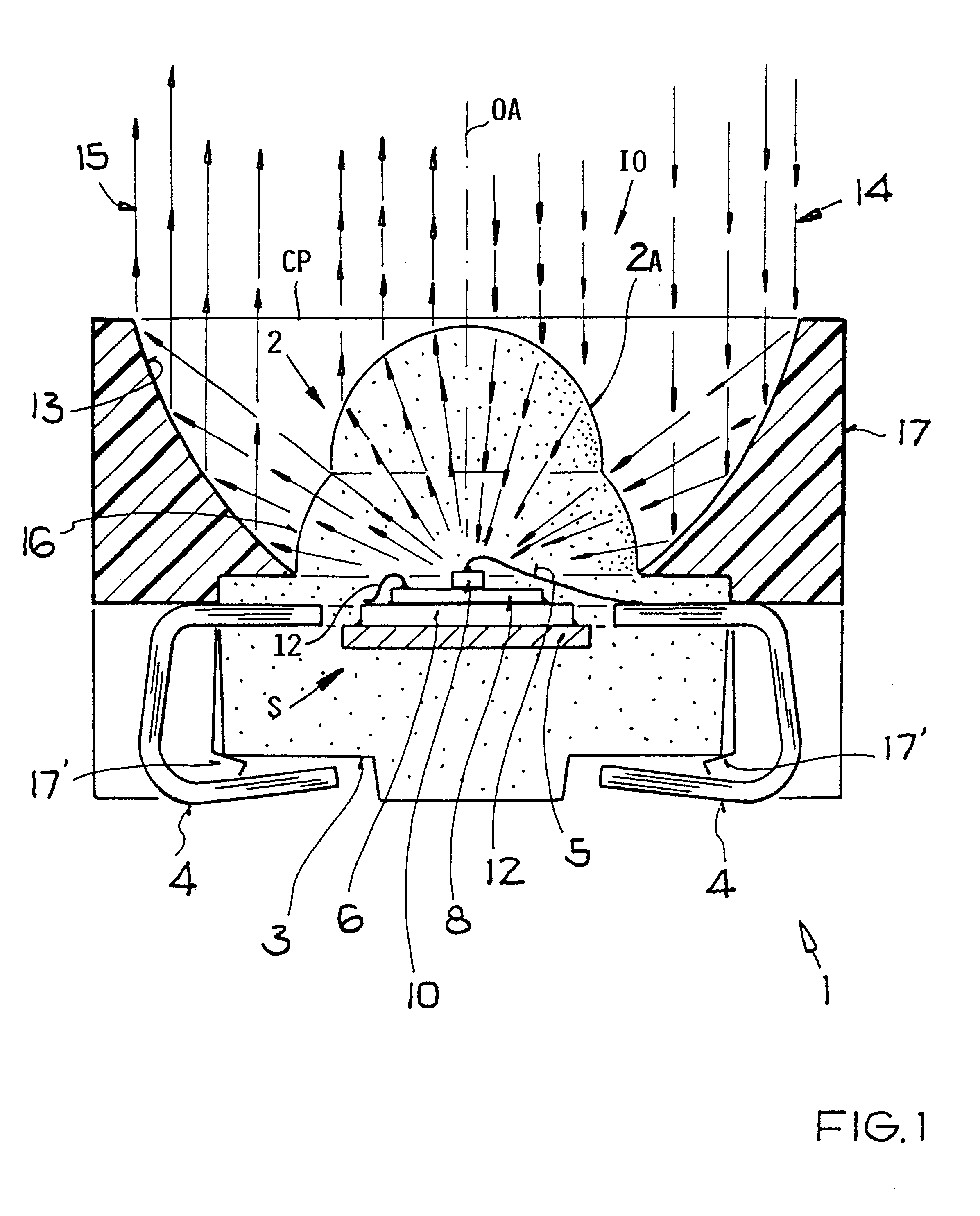
FIGS. 1 and 2 show an infrared transceiver 1 including a lens 2 as an optical system, a housing 3 made of, for example, a thermoplastic or thermosetting material and transparent for IR beams. Terminal pins 4 lead to the outside as part of a metallic strip carrier 5. An integrated circuit 6 is mounted on the carrier 5 for amplifying the signals. A photo PIN diode is arranged as a receiver or detector chip 8 on the integrated circuit 6. The photo PIN diode 8 is a special IrDA product, produced by a technology that is standard for photo PIN diodes.

The transmitter or emitter chip 10 is bonded concentrically onto the detector chip 8. Basically, the transmitter or emitter chip 10 is a known infrared transmission diode. The surface area of the integrated circuit 6 is larger than the surface area of the detector chip 8. The surface area of the detector chip 8 is larger than the surface area of the emitter chip 10. A signal transmission between the emitter chip 10 and the integrated circuit ...


PUM


Abstract

An infrared transceiver for a directed bi-directional optical data transmission through the air has a single-part or multi-part housing in which a stack of components is mounted as follows: an emitter chip for transmitting IR beams, a detector chip for receiving IR beams, and an optical system with a lens and a reflector having an optical axis for focusing the transmitted and received beams. The reflector is arranged concentrically to the optical axis and relative to the components so that transmission power and reception sensitivity of the IR transceiver are increased.

Description

The invention relates to an infrared transceiver for a directed bi-directional optical data transmission through the atmosphere. The transceiver is mounted in a single-part or multi-part housing and includes the following components: an emitter chip for transmitting IR beams, a detector chip for receiving IR beams, and an optical system having an optical axis for focusing the transmitted and received beams.BACKGROUND INFORMATIONSuch a transceiver is used for data transmissions in IrDA applications, For data transmission by means of an optical point-to-point transmission route, the IrDA (Infrared Data Association) standard has been developed. For example, integrated transceiver components known by the designation TFDS 3000 or TFDS 6000 are available from TEMIC TELEFUNKEN microelectronic GmbH, which components correspond to the IrDA standard.Conventionally there are arranged in a common transceiver housing an infrared transmitter (emitter), an infrared receiver (detector), and an inte...

Claims


Application Information

Patent Timeline
IPC IPC(8): H04B10/10H01L31/02H01L33/48H01L33/54H01L33/56H01L33/60H01L33/62H04B10/11
CPCH04B10/11H01L24/45H01L2224/45124H01L2224/45144H01L2224/48091H01L2924/01004H01L2924/01014H01L2924/01058H01L2924/01077H01L2924/01079H01L2924/14H01L2924/00014H01L2924/01068H01L2224/48465H01L2224/73265H01L2924/1815H01L2224/32145H01L2224/48247H01L2924/00H01L2924/12041H01L2924/01013H01L2924/12043H01L2924/181H01L2924/00012
Inventor SCHAIRER, WERNER
Owner VISHAY SEMICON
Why Eureka
Try Eureka