Retainer clip for heat sink for electronic components

Inactive Publication Date: 2001-10-09
PSC COMP PRODS
View PDF7 Cites 36 Cited by
  • Summary
  • Abstract
  • Description
  • Claims
  • Application Information

AI Technical Summary

Benefits of technology

Still another object of the present invention is to provide a heat sink that is very easily inserted so as to secure the heat sink and electronic component to one another, but which may also be easily released in the ev

Problems solved by technology

The latter is particularly a problem since it affects both assembly of the heat sink to the component during initial manufacture of the electronic equipment and throughout the life of the

Method used


Image

  • Retainer clip for heat sink for electronic components
  • Retainer clip for heat sink for electronic components
  • Retainer clip for heat sink for electronic components

Examples


Embodiment Construction

)

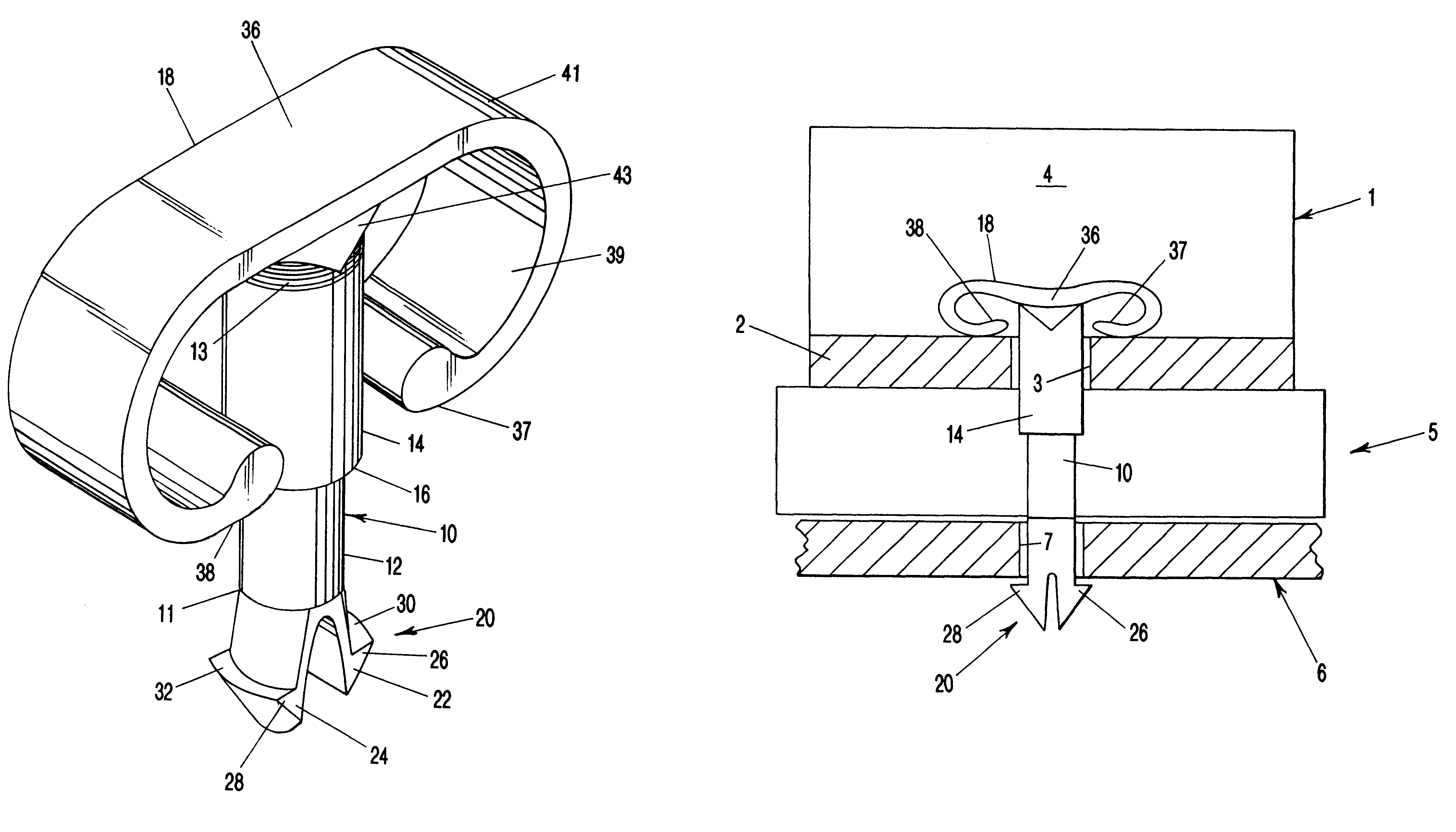
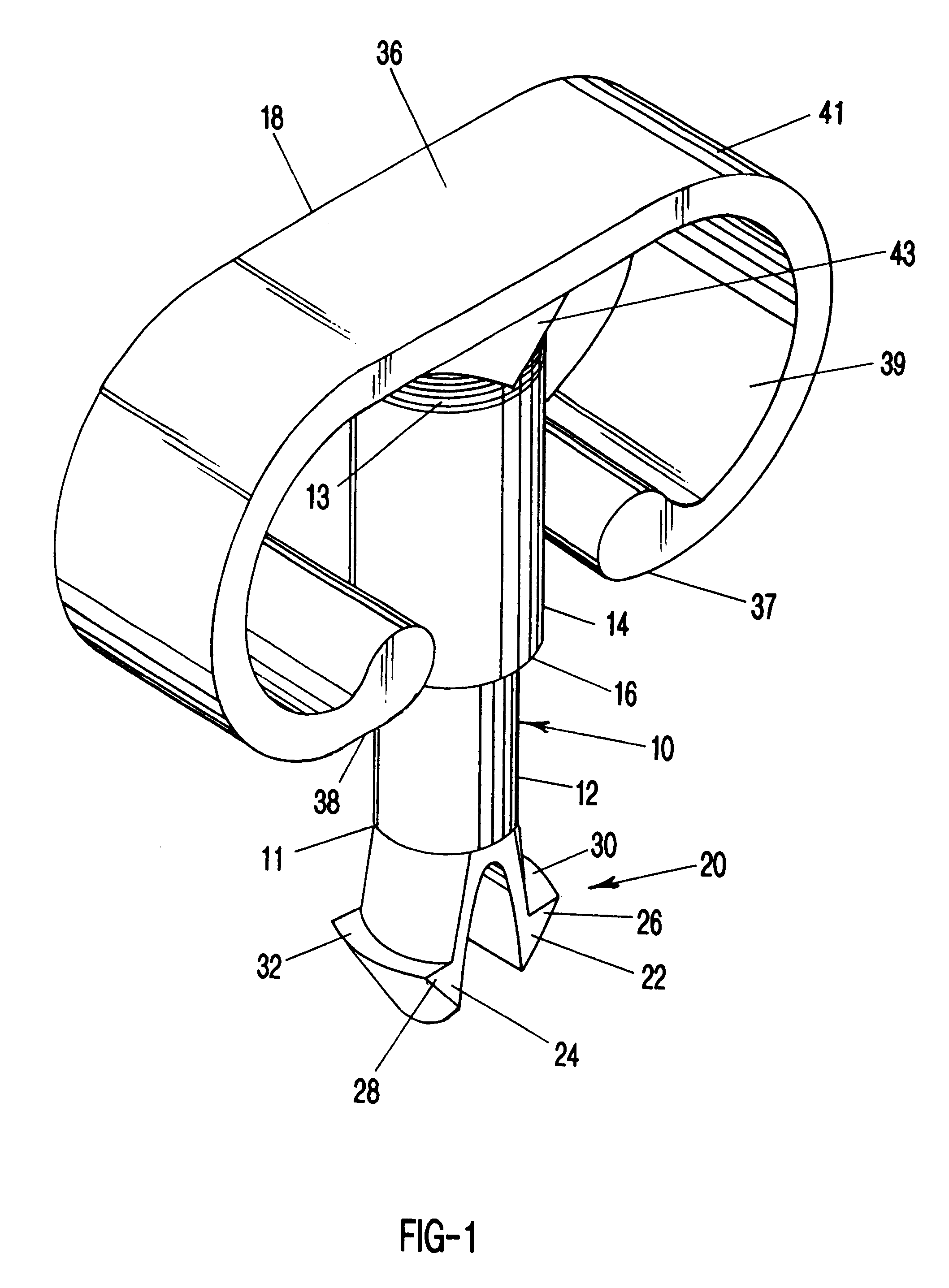
This invention relates to a device for retaining a heat sink in heat conducting relationship with an electronic component, for example, a component mounted on a printed circuit board used in an electronic device such as a computer.

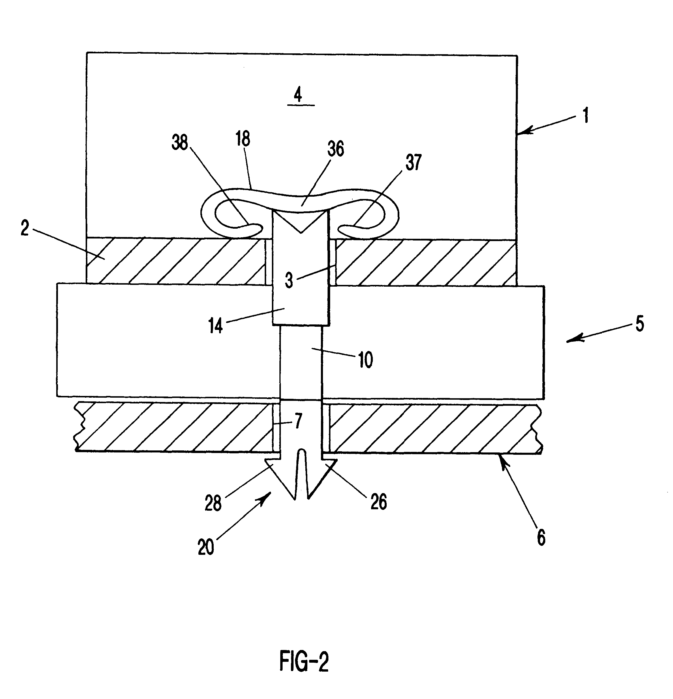
A preferred embodiment of a retainer clip, according to the present invention, is shown in FIG. 1. In this preferred embodiment, the clip comprises a substantially non-electrically conductive material, such as, but not limited to, plastic. In FIGS. 2 and 3, a heat sink as known in the computer and electronic arts is shown. The heat sink 1 shown in FIGS. 2 and 3 is typical and representative of heat sinks used commercially. This heat sink comprises a substantially flat base-plate 2 from which a plurality of fins 4 project upwardly. The fins are optionally integral with the base or otherwise secured to the base. The purpose of the fins is primarily to increase the surface area of the heat sink; other considerations that may influence heat sink design includ...


PUM


Abstract

A retainer clip for retaining a component to a board and a handle for handling the same.

Description

1. Field of the Invention (Technical Field):The present invention relates to retaining devices for heat sinks for electronic components.2. Background Art:Note that the following discussion refers to a number of publications by author(s) and year of publication, and that due to recent publication dates certain publications are not to be considered as prior art vis-a-vis the present invention. Discussion of such publications herein is given for more complete background and is not to be construed as an admission that such publications are prior art for patentability determination purposes.It is well known in the art to use heat sinks for removing heat generated by electronic components in various types of electronic equipment, such as computers, televisions, stereo, etc. Heat sinks are typically formed so as to comprise a flat plate with a plurality of fins disposed at a right angle to the flat plate and preferably formed integral therewith, such as by extrusion or the like. In use, th...

Claims


Application Information

Patent Timeline
IPC IPC(8): H01L23/34H01L23/40H05K7/20F16B21/00F16B21/08
CPCH01L23/4093F16B21/086F16B21/088H01L2924/0002H01L2924/00
Inventor GUERRERO, FRED
Owner PSC COMP PRODS
Why Eureka
Try Eureka