

Speaker
a technology of a speaker and a diaphragm is applied in the field of speakers with an, which can solve the problems of insufficient sound pressure generation, inability to achieve sufficient amplitude in a speaker with a small diaphragm diameter, and inability to achieve a sufficiently large amplitud
- Summary
- Abstract
- Description
- Claims
- Application Information
AI Technical Summary
Benefits of technology
Problems solved by technology
Method used
Image

Examples
example 2
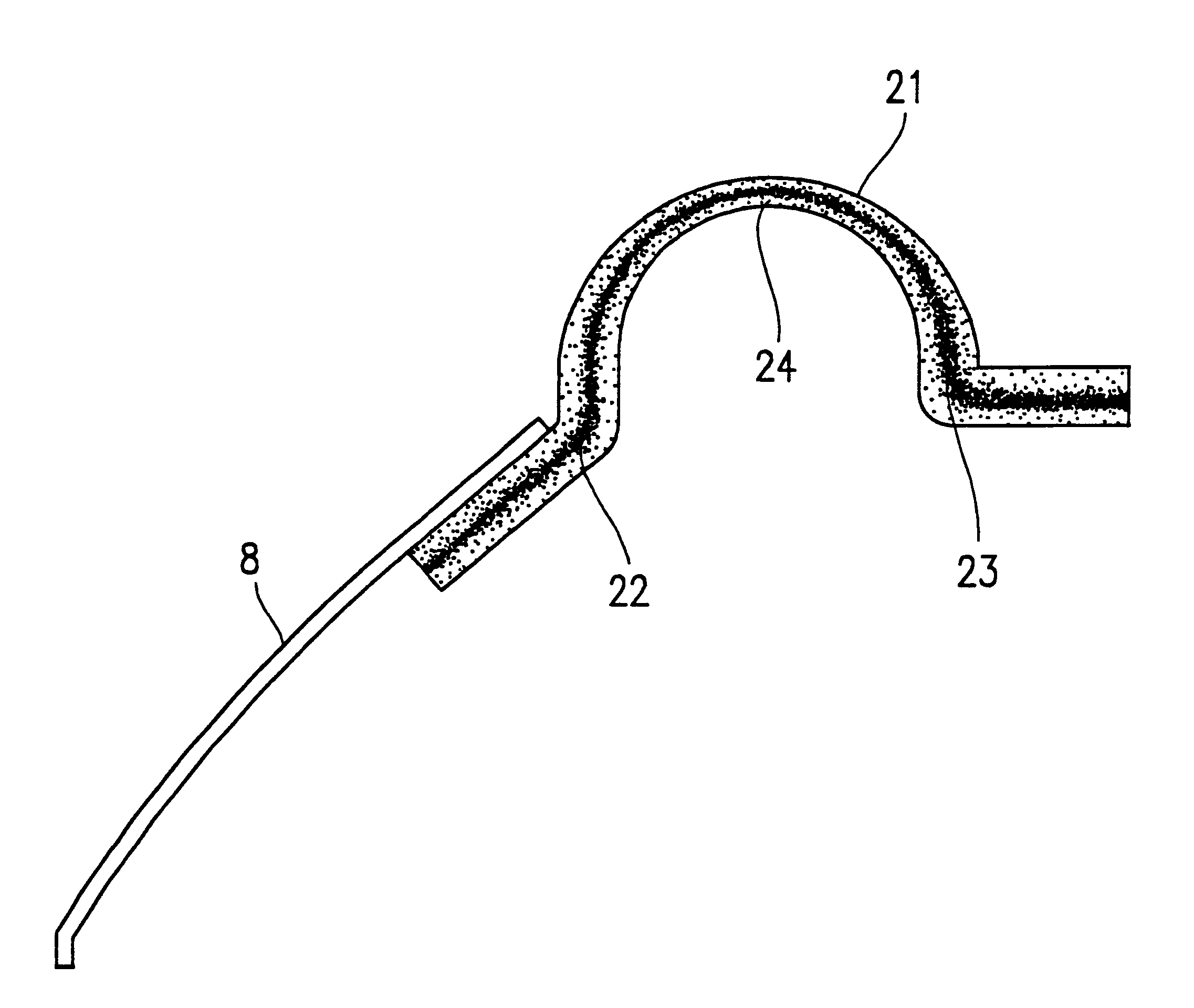
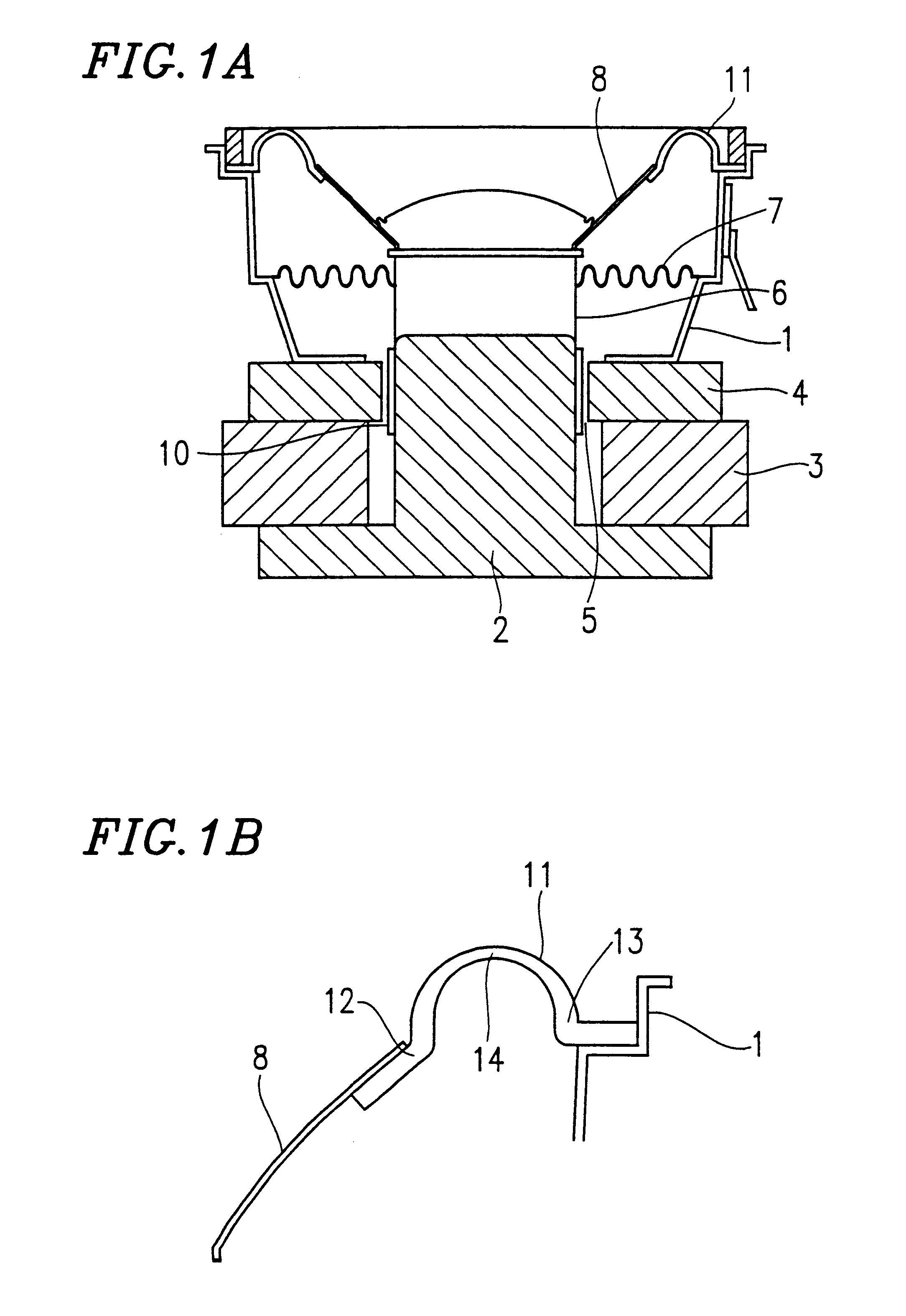
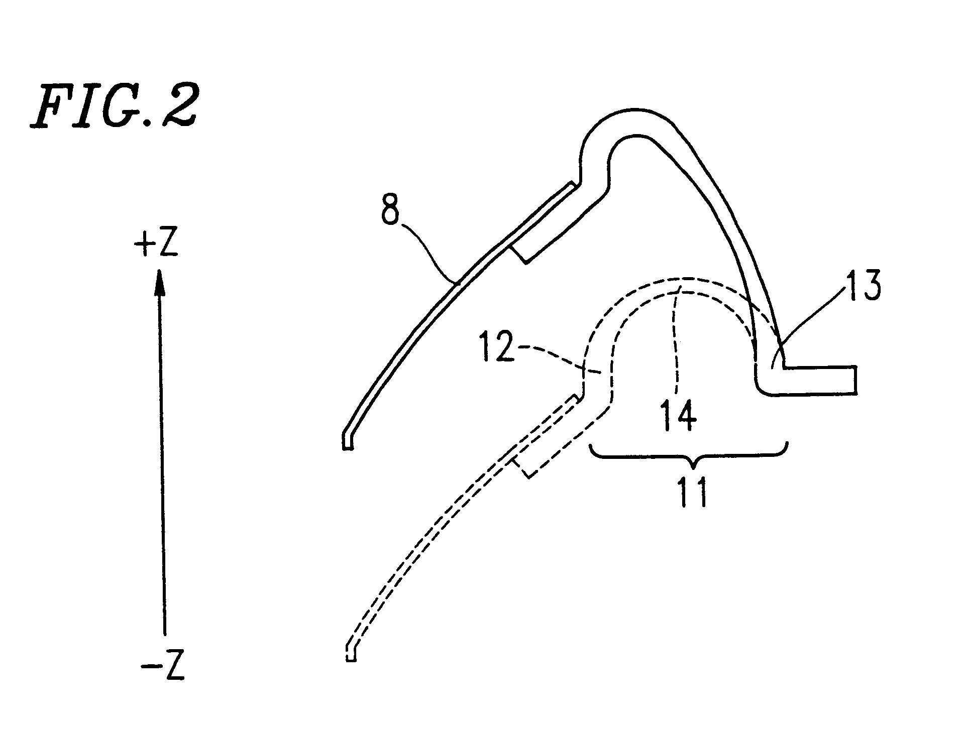
FIG. 5 is an enlarged cross-sectional view of an edge of a speaker in Example 2 according to the present invention. Although a material of an edge 21 of the present example is different from that of the edge 11 of Example 1, the edge 21 has exactly the same shape as the edge 11 of Example 1 and is applied to a speaker in FIG. 1.
A porous rubber foam is used as a material of the edge 21 of the present example, and the edge 21 is formed by molding.
A hollow portion of a mold used for forming the edge 21 has the same shape as an exterior shape of the edge 21. Specifically, a cross-section of the hollow portion is of a roll shape, where a portion corresponding to a top portion 24 of the edge 21 is the thinnest and portions corresponding to an inner peripheral portion 22 and an outer peripheral portion 23 are the thickest. The edge 21 is formed by foaming a rubber material in the hollow portion. A foam magnification (coefficient of volume expansion of a material caused by foaming) of the r...
example 3
FIG. 6A is a cross-sectional view of a speaker in Example 3 according to the present invention. FIG. 6B is an enlarged cross-sectional view illustrating an edge of the speaker and the vicinity thereof in FIG. 6A.
In the present example, an edge 41 has three consecutive roll portions 42, 43, and 44 (FIG. 6B). The roll portion 42 is In the vicinity of an Inner periphery, the roll portion 44 is in the vicinity of an outer periphery, and the roll portion 43 is in a central portion therebetween. The edge 41 is thinnest in a center portion (central portion) and becomes thicker gradually toward the inner peripheral portion 46 and the outer peripheral portion 45. The outer peripheral portion 45 is bonded to the frame 1, and the inner periphery 46 is bonded to the diaphragm 8.
As in the case of Examples 1 and 2, the edge 41 of the present example has both the advantage of being flexible and easily deformed in a certain range of a vibration amplitude of the diaphragm 8, and the advantage of not...
example 4
FIG. 7A is a cross-sectional view of a speaker in Example 4 according to the present invention. FIG. 7B is an enlarged cross-sectional view illustrating an edge of the speaker and the vicinity thereof In FIG. 7A.
An edge 51 of the present example has three consecutive roll portions 52, 53, and 54. The roll portion 52 Is in the vicinity of an inner periphery, the roll portion 54 is in the vicinity of an outer periphery, and the roll portion 53 is in a central portion therebetween. A radius of the roll portions 52 and 54 is smaller than that of the roll portion 53. As a radius of a roll portion decreases, a stiffness of the edge for retaining a diaphragm 8 rises, thereby reducing an amount of displacement of the roll portion in response to a force (N) applied to an inner peripheral portion of the edge 51. Reducing the radius has the same effect as increasing a thickness of the edge. Thus, the edge 51 of the present example has the roll portion 53 in the center, which is flexible and ea...
PUM
 Abstract
Description
Claims
Application Information