Connection assembly of printed-circuit board and connector and an electronic-equipment plug-in card provided with same

a technology which is applied in the direction of fixed connections, coupling device connections, electrical apparatus construction details, etc., can solve the problems of affecting the reliability of electrical equipment, and consuming a lot of time, and achieves the effect of accurate fixing of printed circuit boards and connectors and easy production

Inactive Publication Date: 2001-10-23
ITT CANNON
View PDF9 Cites 21 Cited by
  • Summary
  • Abstract
  • Description
  • Claims
  • Application Information

AI Technical Summary

Benefits of technology

The problem addressed by the present invention is to create a connection of a printed-circuit board and connector with an electronic-equipment plug-in card provided with same, e

Problems solved by technology

This manner of holding or positionally fixing a printed-circuit board and connector relatively to one another prior to production of the soldered connection is relatively time-consuming and costly

Method used


Image

  • Connection assembly of printed-circuit board and connector and an electronic-equipment plug-in card provided with same
  • Connection assembly of printed-circuit board and connector and an electronic-equipment plug-in card provided with same
  • Connection assembly of printed-circuit board and connector and an electronic-equipment plug-in card provided with same

Examples


Embodiment Construction

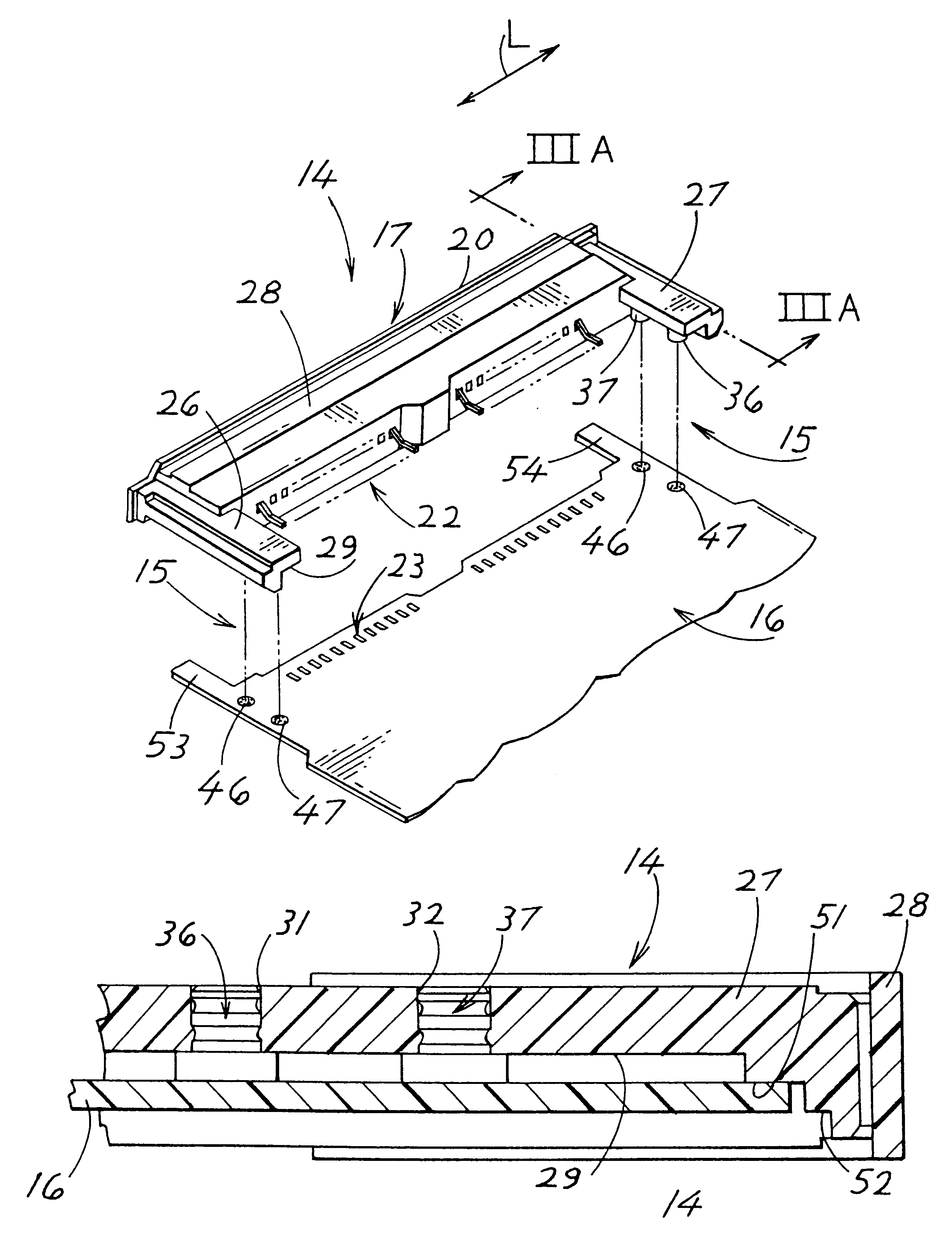
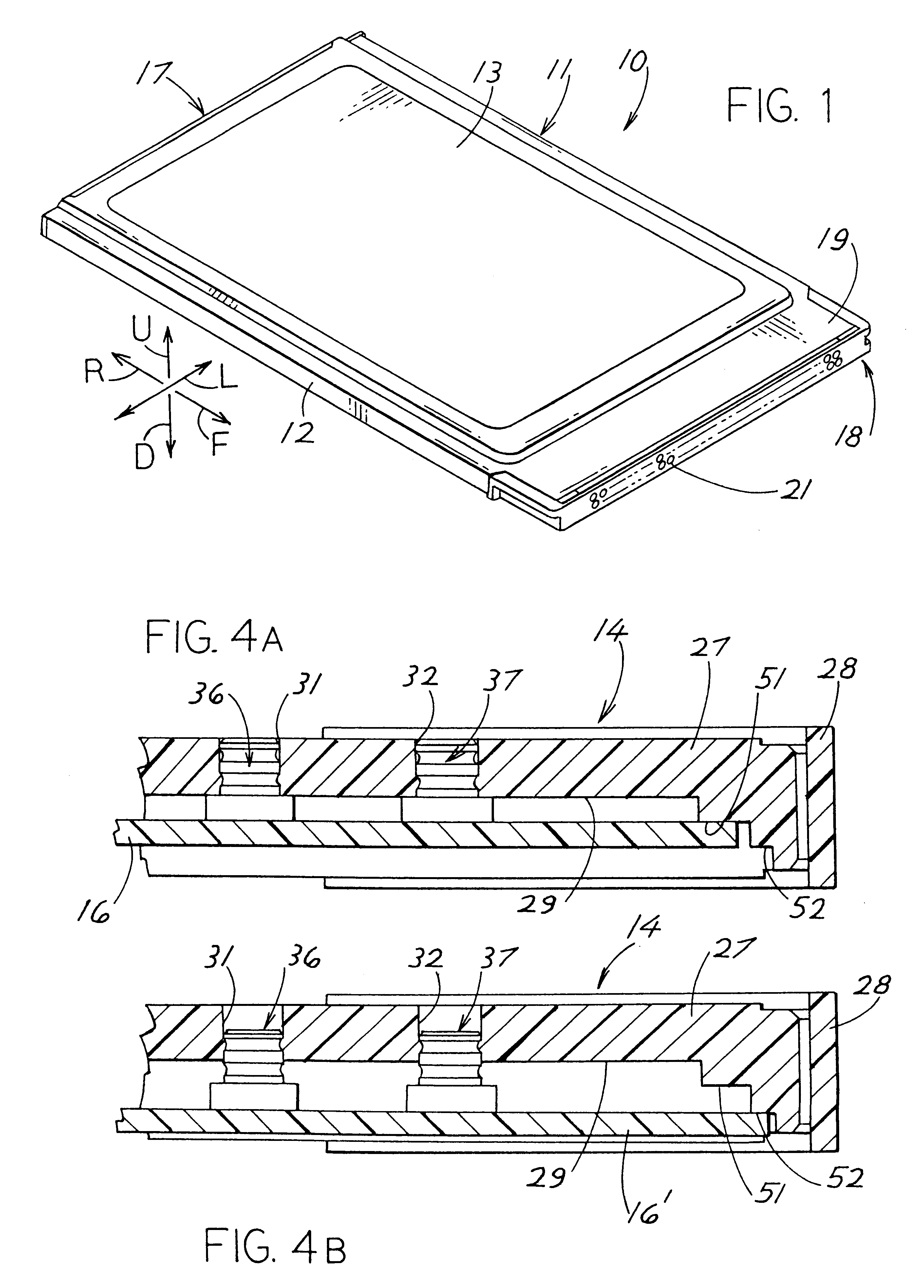
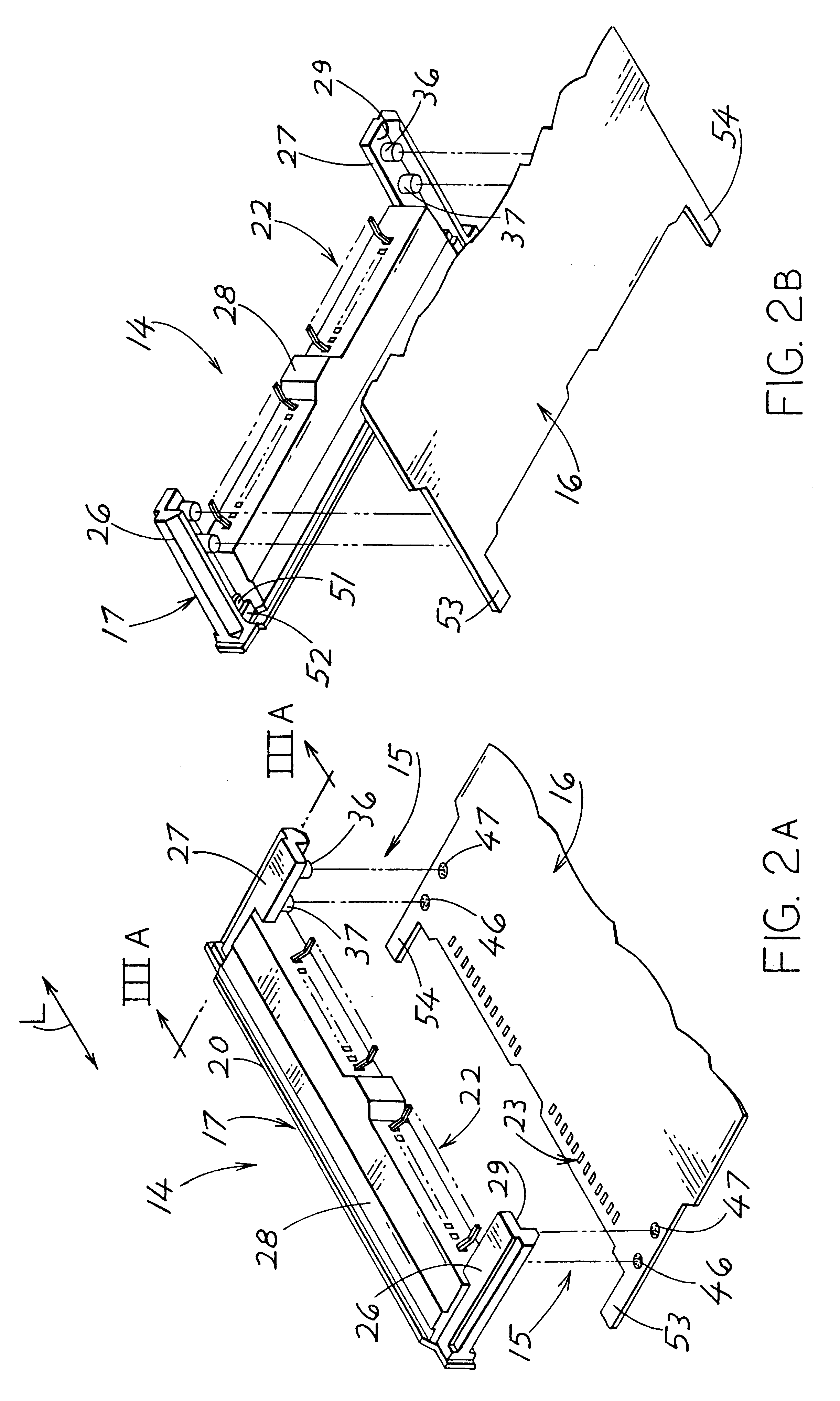
The frameless electronic-equipment plug-in card 10 which is shown in assembled condition in FIG. 1, has front and rear ends spaced in directions F, R, has laterally opposite sides spaced in lateral directions L, and has upper and lower portions spaced in directions U, D. The card has an elongated, rectangular, very flat enclosure 11, which is comprised of a recessed bottom enclosure section 12 and a recessed top enclosure section 13 connected to latch with the former. Front and rear spacers, or connectors 18, 17 lie at the ends of the cards. Between the two enclosure sections 12 and 13 there is arranged and fixed in place a unit 14 (FIG. 2A) only partially represented in each case, which has an approximately elongated, rectangular printed-circuit board 16 fitted, although this is not illustrated, with electronic components and two spacers 17 and 18 arranged one at each transverse end of the printed-circuit board 16 and connected to same, both of which are designed as connectors. The...


PUM


Abstract

In a connection assembly (15) of printed-circuit board and connector, a printed-circuit board (16) and a connector (17) can be fixed positionally accurately in relation to one another by means of position holders (36, 37) provided on the connector (17). The position holders are constituted of soldering pins (36, 37) and the printed-circuit board (16) is provided with soldering pads (46, 47) which can be connected to the opposing soldering pins (36, 37) by soldering. There is provided in this manner a connection assembly (15) of printed-circuit board and connector in which the positionally accurate fixing of a printed-circuit board (16) and a connector (17) is more easily produced and more precisely assembled than has been possible to date.

Description

CROSS REFERENCEApplicant claims priority from German patent application 19514121.0 filed Aug. 20, 1995 and German patent application 19540540.4 filed Oct. 31, 1995.BACKGROUND OF THE INVENTIONThe present invention relates to a connection assembly and to an electronic-equipment plug-in card provided with same.The connection of a printed-circuit board and a connector necessitates accurate positioning of the two components in relation to one another, because on account of the general confined basic connection grid, the connecting lugs of the connector must coincided precisely in position with the connecting tracks of the printed-circuit board for soldering purposes. To date, this positionally accurate fixing of the connector on the printed-circuit board or vice versa is produced by moulding pegs onto the connector as position holders, which pegs can be plugged into locating holes in the appropriate areas of the printed-circuit board. Connectors referred to as MPC connectors can be consi...

Claims


Application Information

Patent Timeline
IPC IPC(8): H05K3/34H01R12/55
CPCH05K3/3405H01R12/7064H05K3/341H05K2201/09781H05K2201/10189
Inventor BAGINY, MICHAEL DUANELEARMONTH, IAIN THOMASMICHAELIS, SEPP-DIETERBIERMANN, WERNER
Owner ITT CANNON
Why Eureka
Try Eureka