Handle for household utensils

a technology for household appliances and handles, applied in the field of handles for household appliances, can solve the problems of user's hands being blistered, and achieve the effects of enhancing friction, enhancing friction, and length of the handle to be changed

Inactive Publication Date: 2001-11-06
CARL FREUDENBERG KG
View PDF8 Cites 41 Cited by
  • Summary
  • Abstract
  • Description
  • Claims
  • Application Information

AI Technical Summary

Benefits of technology

is to create a handle for household implements that avoids these disadvantages.
With a polygonal outer contour, consisting of faces and edges, the user's hand can get a purchase on the faces, and bring about a sort of geometrical hold on the edges. The required grip for the frictional hold can be reduced, thus countering the blistering hazard. The handle may consist of wood, plastic, metal or other material.
To reduce weight, the handle is hollow, its inner contour matching its outer contour. Preferably metal or plastic is used as material.
So that the length of the handle may be varied, the handle comprises several releasably interconnected segments of like outer contour, with coupling elements arranged in the hollow interior. The coupling elements partly project beyond the segment in order to engage the next following segment. This multipartite construction has advantages also in transport of the handle, namely a much shorter length than the assembled handle. Owing to the polygonal inner contour of the segments, the coupling element engaged by the polygonal contour is geometrically secured against rotation, so that no additional security measures, for example bonding, are required to transmit the torque. The catch means provided in the coupling element for axial fixation of the segments in relation to each other are not loaded rotationally but only axially.
In a modification, the handle consists of a guide tube and a telescoping rod guided therein, the telescoping rod having an outer contour of smaller size matching the guide tube in shape and being fixed in various positions in the guide tube by means of a catch device. With telescoping handles, a variable change of handle length is possible. Compared to known telescoping handles, the advantage consists in that the catch device need assume only axial forces, since the rotary motion is transmitted geometrically. For known handles, where the telescoping rod is locked by tightening on a taper, there is danger that the user operating the household implement may not note the direction of rotation of the rotary motion, thus releasing the taper.
Another modification consists in that the end of the handle near the user is provided with a fixable cap guided axially displaceable with respect to the end of the handle and held in at least two positions. This enables the length of the handle to be changed. Here again, use is made of geometrical fixation to transmit the rotary motion, by way of improving the rotary loadability of a cap disclosed in DE GM 94 107 91. The catch device is here likewise stressed lengthwise only.

Problems solved by technology

These handles have the disadvantage that when a rotary motion, either isolated or superimposed on a wiping motion, is transmitted, the user effects the transmission solely by a firm grip around the handle, thus producing a friction link.
Furthermore, there is the danger of blistering of the user's hands when rotating the handle by friction, since different skin layers may be displaced relative to each other.

Method used


Image

  • Handle for household utensils
  • Handle for household utensils
  • Handle for household utensils

Examples


Embodiment Construction

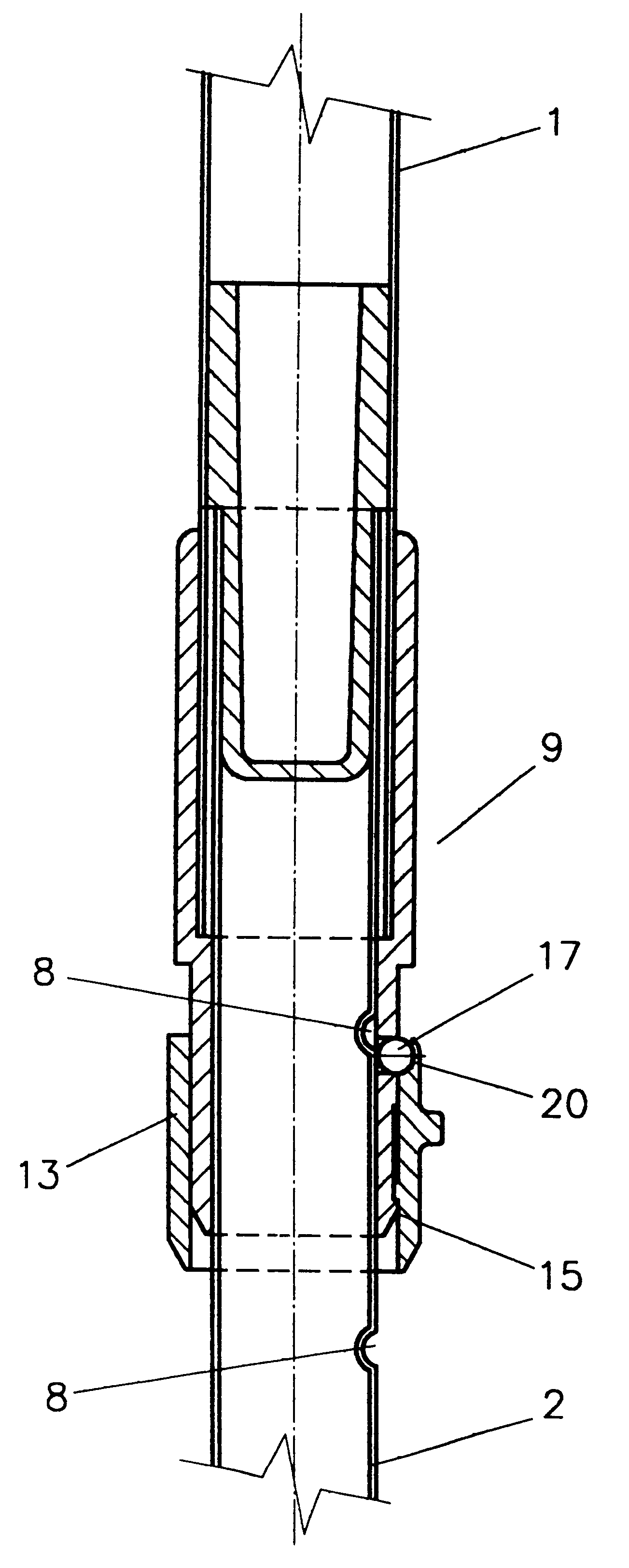
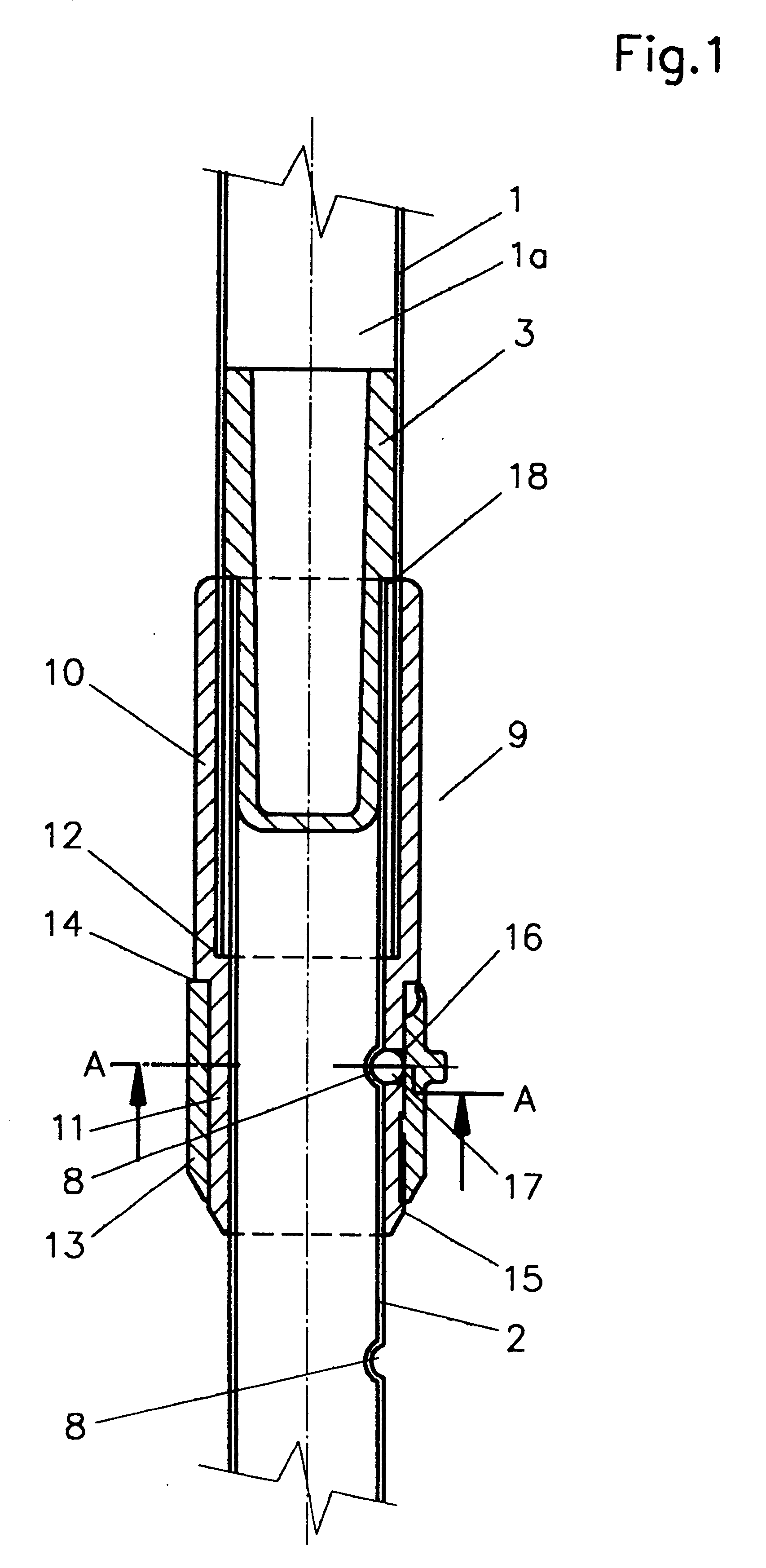
In FIG. 1, a telescoping handle of metal is represented, comprising a guide tube 1 and a telescoping tube 2. The telescoping tube 2 projects into a cavity 1a of the guide tube 1 and is guided therein by means of a guide part 3. The guide part 3 is fixed in turn in the hollow telescoping tube 2.

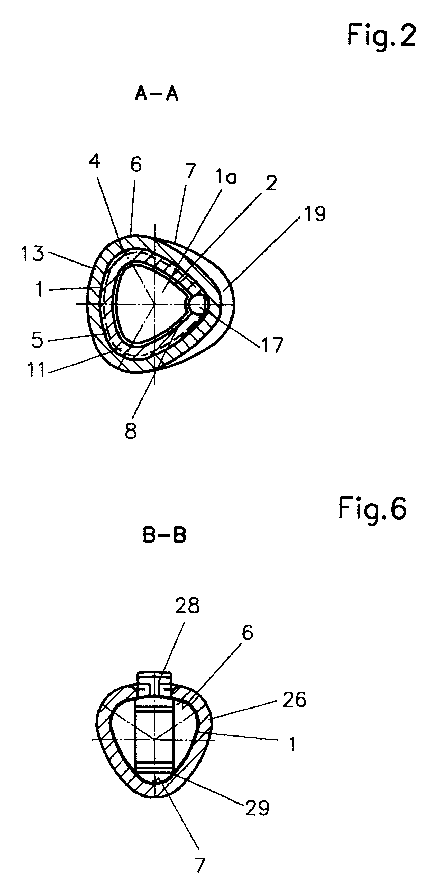
Both the outer contour 4 and the inner contour 5 of the guide tube 1 and of the telescoping tube 2 have the configuration of a polygon having three somewhat concavely curved faces and three very concavely curved edges 7 (FIG. 2).

The telescoping tube 2 is provided at one end 7 with indentations 8 arranged at regular intervals. It is immaterial just where the indentations 8 are located. The indentations 8 cooperate with a fixation device 9 represented in FIG. 1.

The fixation device 9 is placed on the end of the guide tube 1 accommodating the telescoping tube 2, and comprises a first segment 10 snugly enclosing the guide tube, The segment 10 is connected to the guide tube 1 by friction. The segmen...


PUM


Abstract

Disclosed is a handle for household utensils, in particular for floor cleaning utensils, the external polygonal contour of which presents side faces (6) and edges (7).

Description

FIELDThe invention relates to a handle for household implements, in particular floor care implements, in the operation of which a rotary motion must also be transmitted by way of the handle.PRIOR ARTThe mop handles heretofore employed by Applicant comprise a round outer contour, corresponding to the turned wooden handles or round handles of metal or plastic for brooms, scrubbers or the like.These handles have the disadvantage that when a rotary motion, either isolated or superimposed on a wiping motion, is transmitted, the user effects the transmission solely by a firm grip around the handle, thus producing a friction link. A rotary motion is required for example in order to press a mop into contact with a sieve suspended over the pail.Especially in use of household implements designed for wet application, after wringing, out by hand the film of moisture greatly reduces the friction, so that an additional exertion of force is required to produce the rotary motion.Furthermore, there ...

Claims


Application Information

Patent Timeline
Patent Type & Authority Patents(United States)
IPC IPC(8): B25G1/04B25G3/26B25G3/18B25G1/00B25G3/00A47L13/42B25G1/10
CPCB25G1/04B25G1/102B25G3/26B25G3/18Y10T16/4719Y10T16/473
Inventor SARTORI, FRANCESCO
Owner CARL FREUDENBERG KG
Why Eureka
Try Eureka