
Sanding disks

a technology of sanding disks and disks, which is applied in the direction of gear teeth, gear teeth, manufacturing tools, etc., can solve the problems of unsatisfactory scalloped surface of work surfaces, inability to use disks for finely controlled work, and sanding block treatment, so as to protect users from injury

Inactive Publication Date: 2001-11-06
MORTON CO
View PDF13 Cites 90 Cited by
  • Summary
  • Abstract
  • Description
  • Claims
  • Application Information

AI Technical Summary

Benefits of technology

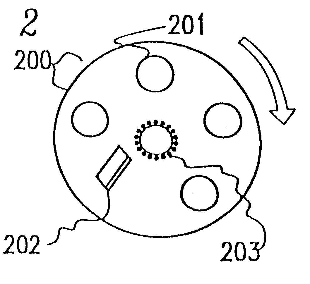
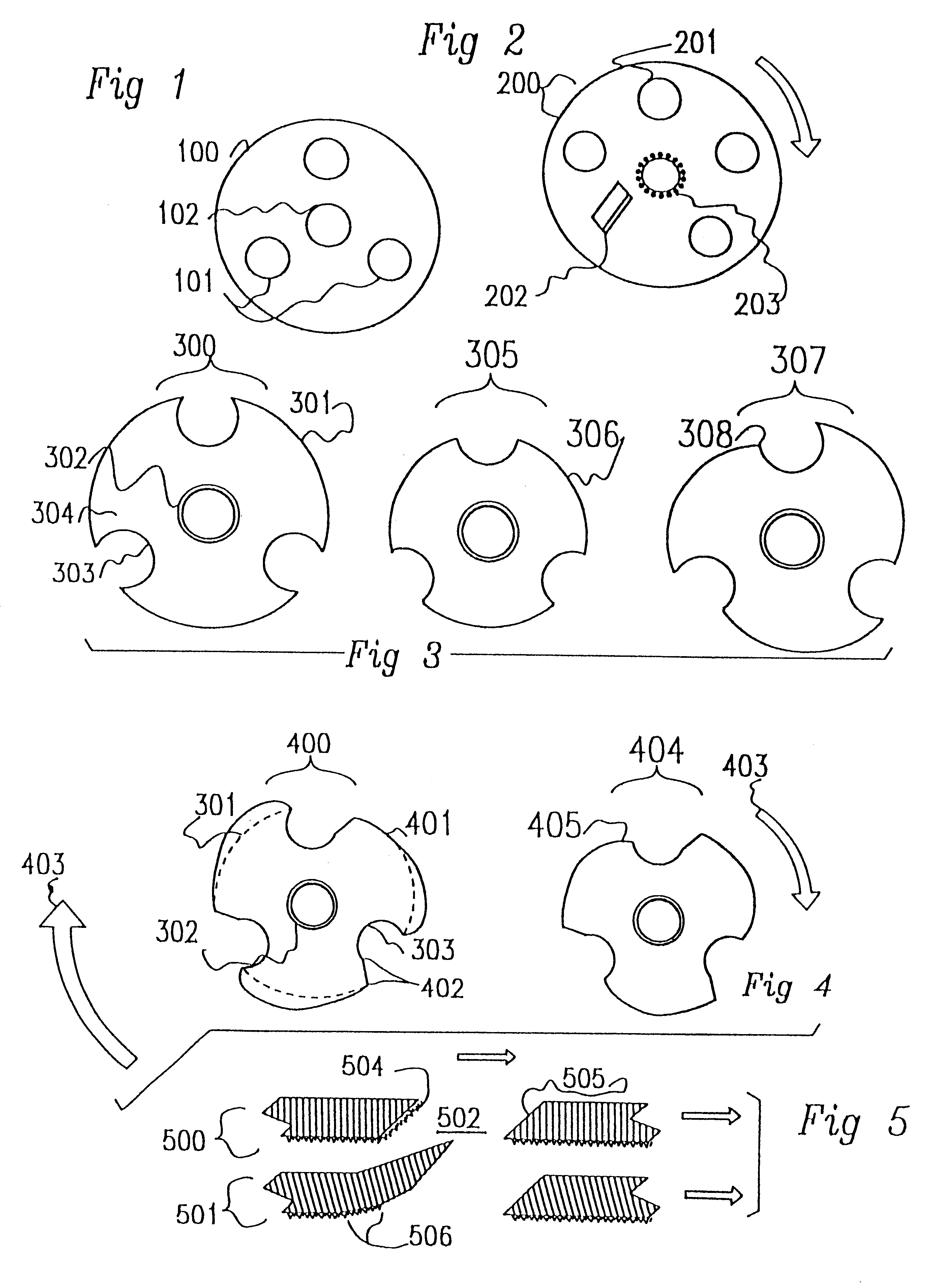
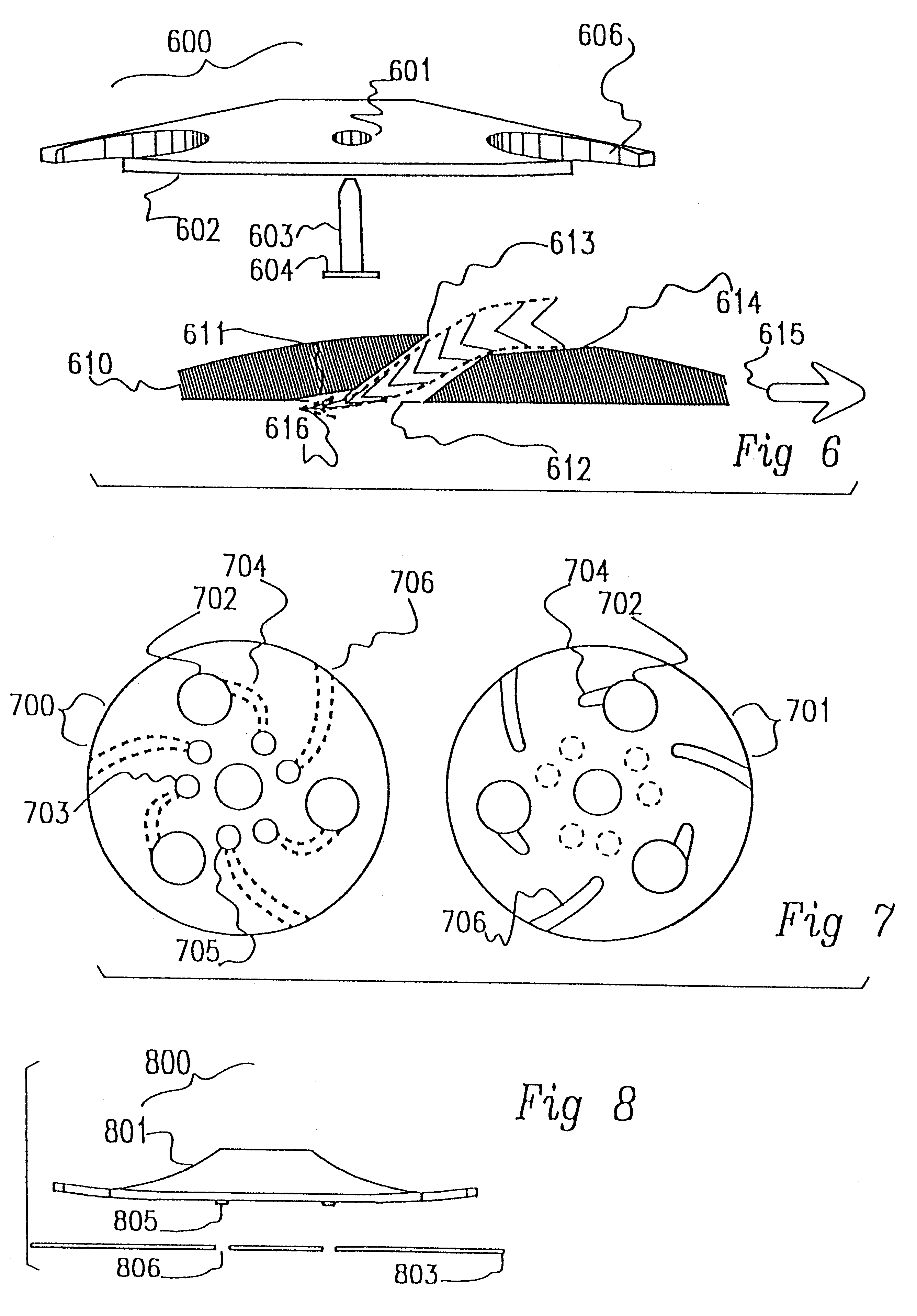
Preferably the non-concentric apertures adapted for viewing and ventilation are placed at varying distances from the centre of rotation of the sanding disk, so that when the disk is rotated, a substantial proportion of the area beneath the disk can be seen. Rotation of the disk defines leading and trailing edges of the apertures and it is a feature of this invention that the trailing edge of each aperture is displaced out of the plane of the abrading surface of the disk and towards the back of the disk. This has the effect of minimizing the risk that protrusions from the surface being abraded will catch on the edge of the disk and cause rupture of the disk.
Preferably the invention also provides a guard for an angle grinder, adapted to protect the user from injury resulting from the spinning sanding disk and / or the backing plate; the guard comprising a protective cover mounted at least one of the threaded sockets for the gripping handle and projecting forwards between the sanding disk and the operator.

Problems solved by technology

(a) The relatively rigid backing disks commonly used with angle grinder sanding disks force the sanding disks into an unsatisfactory mode of operation when the angle grinder is tilted towards the work during use--such as that primarily the edge engages with the work resulting in local, intense action rather than an even, gradual action over a wider area. There is a tendency for the work surface to develop an unsatisfactory scalloped surface which requires hand sanding block treatment. The disks cannot be used for finely controlled work such as preparation of surfaces in a state ready for painting.
(b) Sometimes the material being abraded tends to melt at the high cutting speeds involved, and if this happens it is particularly likely to clog the sanding disk in a quick and effective manner so that the disk has to be discarded. Melting may also lead to the tool biting in and as a result the surface of the work may be inadvertently destroyed. Heating also adversely affects the life of the sanding disk.
(c) The operator cannot see the material being sanded during the actual operation; he / she can only see material that is not covered by the blade. It is difficult to carry out a precise operation without repeatedly inspecting the work in progress and more closely reaching an approximation to the desired result. Hand-held tools cannot be re-applied precisely so that repeated inspection is not a good option for careful work.

Method used


Image

  • Sanding disks
  • Sanding disks
  • Sanding disks

Examples


example

In this Example the advantages of the disks in which chord segments are removed to produce an abrasive disk. In this Example, four disks are compared for grinding performance. The first disk, (D), is a prior art disk with a diameter of 11.4 cm (4.5 inches) with a central mounting aperture used in the typical prior art fashion with only the outer periphery actually used for grinding. This was done by having the area of contact on the workpiece overlap the perimeter. The second, (B) was identical to the D disk except that full contact was maintain with the full workpiece by moving the location of engagement between the disk and the workpiece to the same location used with the other disks. The third disk, (C), was an identical disk but modified to make it according to the invention by being provided with three viewing apertures as shown in FIG. 24 (2400) of the drawings except for the omission of features 2401 and 2402. The fourth disk, (A), was a disk similar to disk C except that cho...


PUM


Abstract

Accessories for an angle grinder include a disposable rotary sanding disk having quite large shaped ventilating / viewing apertures, for use with a resilient backing plate also having shaped ventilating apertures. The apertures of one or both parts are shaped so that snagging of the apertures on projections from the work surface is minimized and to facilitate air flow across the work surface during use. This air flow helps in cooling the work and ejecting detritus, so minimising clogging effects. The ventilating apertures also facilitate viewing the work to be sanded through the spinning disk during the abrasion process, so that operator feedback is immediate. The holes also give the sanding disk more resilience so that a greater area comes in contact with the work and the disk wears more evenly over its abrasive surface.

Description

This invention relates to the field of abrasive or sanding disks, and in particular this invention relates to sanding disks and accessories for angle grinders and means for making them.Abrasive disks, or sanding disks are widely used on portable electric drills and (at a more professional level) on hand-held angle grinders. When used on these machines the disk is held by its centre against a backing pad and is rotated at generally a high speed while pressed in front of a backing plate against the work. The abrasive surface wears down the surface of the work by, in effect, a cutting action. Angle-grinder mounted sanding disks are commonly used (for example) in automotive panel beating, where body filler is to be sanded back to conform to the original contours of a remodelled car part. It is said that millions of sanding disks suitable for use with angle grinders are sold each year. There are some problems related to the use of sanding disks, such as:(a) The relatively rigid backing d...

Claims


Application Information

Patent Timeline
Patent Type & Authority Patents(United States)
IPC IPC(8): B24D9/00B24D7/10B24D7/00B24D9/08B24D7/12B24B23/00B24D13/04B24D13/16B24D99/00
CPCB24D7/10B24D7/12B24D9/08
Inventor VAN OSENBRUGGEN, ANTHONY ALFRED
Owner MORTON CO
Learn More