Method for arc welding with melting electrode

a technology of melting electrodes and arc welding, which is applied in the direction of arc welding apparatus, welding equipment, manufacturing tools, etc., can solve the problems of poor repeatability, considerable demands on the skill of welders, and material in the centre of the molten pool

Inactive Publication Date: 2001-11-06
ESAB AB
View PDF11 Cites 31 Cited by
  • Summary
  • Abstract
  • Description
  • Claims
  • Application Information

AI Technical Summary

Benefits of technology

The object of the invention is to suggest a novel method in manual or automated arc welding operations that use a melting/consumable electrode, of controlling a source of welding current and the as

Problems solved by technology

Particularly in the case of high-energy supply welding with consequential large molten pools, there is a deficiency of material in the centre of the molten pool as the molten material solidifies.
Often, this pipe also is the origin of fissures or cracks e

Method used


Image

  • Method for arc welding with melting electrode
  • Method for arc welding with melting electrode

Examples


Embodiment Construction

For exemplifying purposes, the invention will be described in more detail in the following with reference to the accompanying drawings.

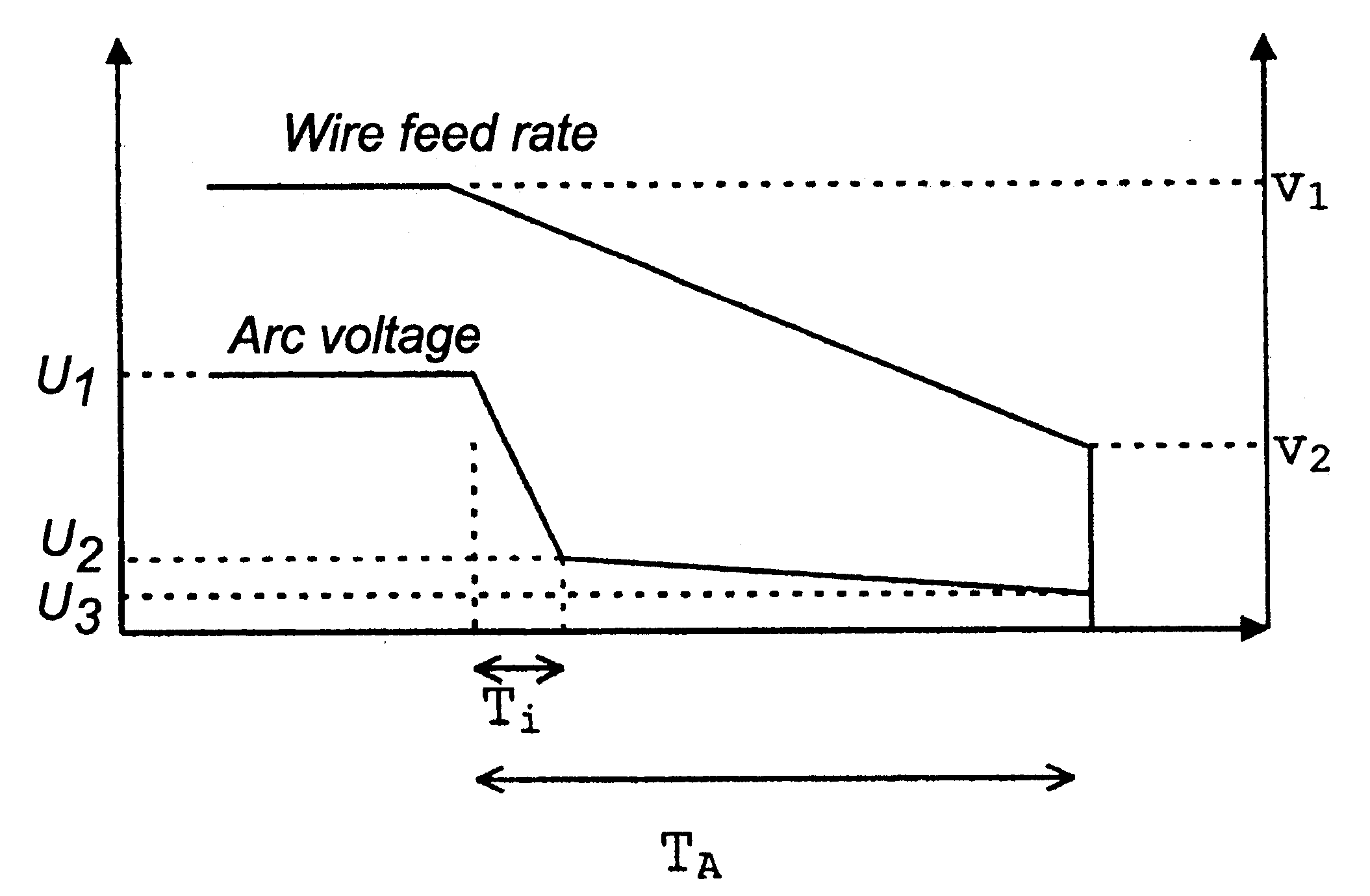
The invention is concerned with the end of a welding operation wherein arc voltage and feed rate are faded during a weld finishing period, i.e. are reduced, to a minimum value at which the welding operation is interrupted.

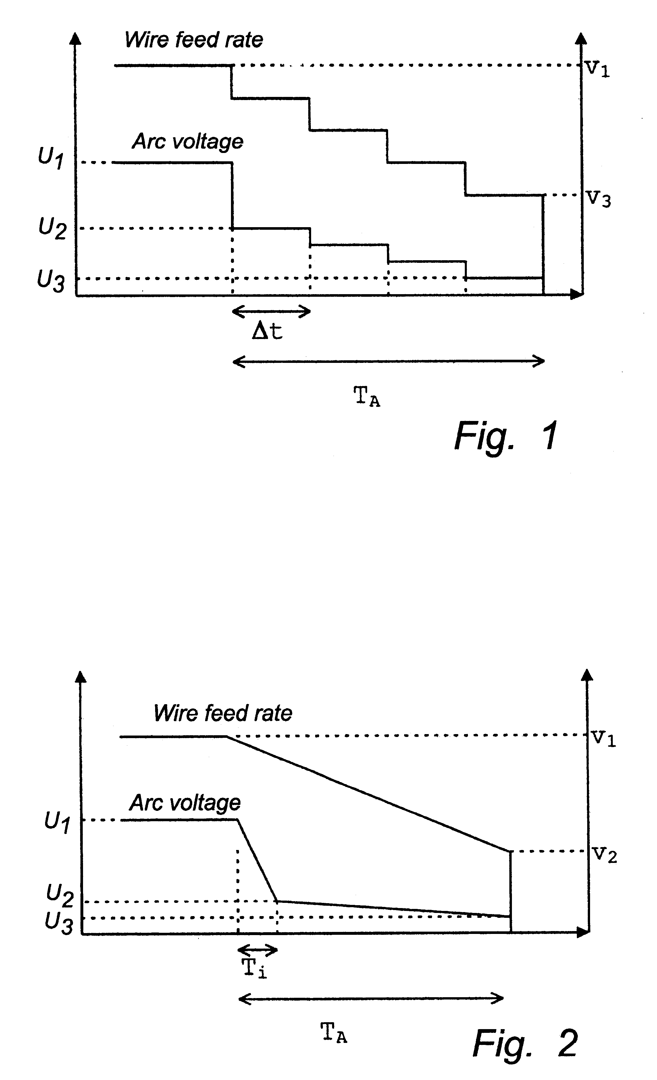
In accordance with the invention an initial arc voltage reduction is effected in the initial stage of the end of the welding operation for a period that is considerably shorter than the total fading period, whereupon a further reduction is effected until a final arc-voltage value is obtained. At the same time also the wire feed rate is faded to a final value, simultaneously with the arc-voltage fading. The latter fading of the wire feed rate preferably is continuous or divided into essentially equal steps.

In accordance with a first embodiment, illustrated in FIG. 1, the fading of the wire feed rate v as well as of the arc voltage U ...


PUM

PropertyMeasurementUnit
Fractionaaaaaaaaaa
Fractionaaaaaaaaaa
Timeaaaaaaaaaa

Abstract

The present invention relates to a method of controlling a welding power source and the associated wire feed arrangement intended for arc welding operations that employ a consumable electrode, to ensure crater filling at the end of the welding operation by means of fading of the arc voltage and of the wire feed rate, respectively. More particularly the invention relates to a method comprising arc voltage reduction at the onset of the end of the welding operation for a period that is considerably briefer than the total fading time, during which the arc voltage is reduced to a value below the value at which it is possible to weld during continuous welding and advancement in the joint with otherwise unchanged welding parameters, followed by a further reduction to a final value of arc voltage and fading of the wire feed rate simultaneously with the arc voltage fading to a final value of the wire feed rate.

Description

The present invention relates to a method in manual or automatic arc welding, of controlling the end of the welding process to ensure that the crater formed in the welding operation is minimised.In arc welding, a depression forms in the molten pool from the pressure of the arc and the material transferred by the arc from the electrode to the work-piece. This depression is often referred to as the crater. At the end of the welding operation, this crater remains in the shape of an end crater. When the energy supply ceases abruptly at the end of the welding operation the molten material solidifies while shrinking. The solidification starts at the weld edges and progresses towards the centre. Particularly in the case of high-energy supply welding with consequential large molten pools, there is a deficiency of material in the centre of the molten pool as the molten material solidifies. As a result, a so called pipe forms, i.e. a hole extending vertically through the end crater. Often, th...

Claims


Application Information

Patent Timeline
IPC IPC(8): B23K9/06B23K9/073B23K9/12
CPCB23K9/0731B23K9/124
Inventor SOTING, TORANG.BERG, PER
Owner ESAB AB
Why Eureka
Try Eureka