Apparatus and method for transmitting information and apparatus and method for receiving information

a technology of information transmission and apparatus, applied in the field of transmitter receiver system, can solve the problem of direct system cost reduction of transmitter power

Inactive Publication Date: 2001-11-06
FRAUNHOFER GESELLSCHAFT ZUR FOERDERUNG DER ANGEWANDTEN FORSCHUNG EV
View PDF18 Cites 146 Cited by
  • Summary
  • Abstract
  • Description
  • Claims
  • Application Information

AI Technical Summary

Problems solved by technology

Reduced transmitter power directly translates into system costs.
Therefore, the system described in FIG. 7 is disadvant...

Method used


Image

  • Apparatus and method for transmitting information and apparatus and method for receiving information
  • Apparatus and method for transmitting information and apparatus and method for receiving information
  • Apparatus and method for transmitting information and apparatus and method for receiving information

Examples


Embodiment Construction

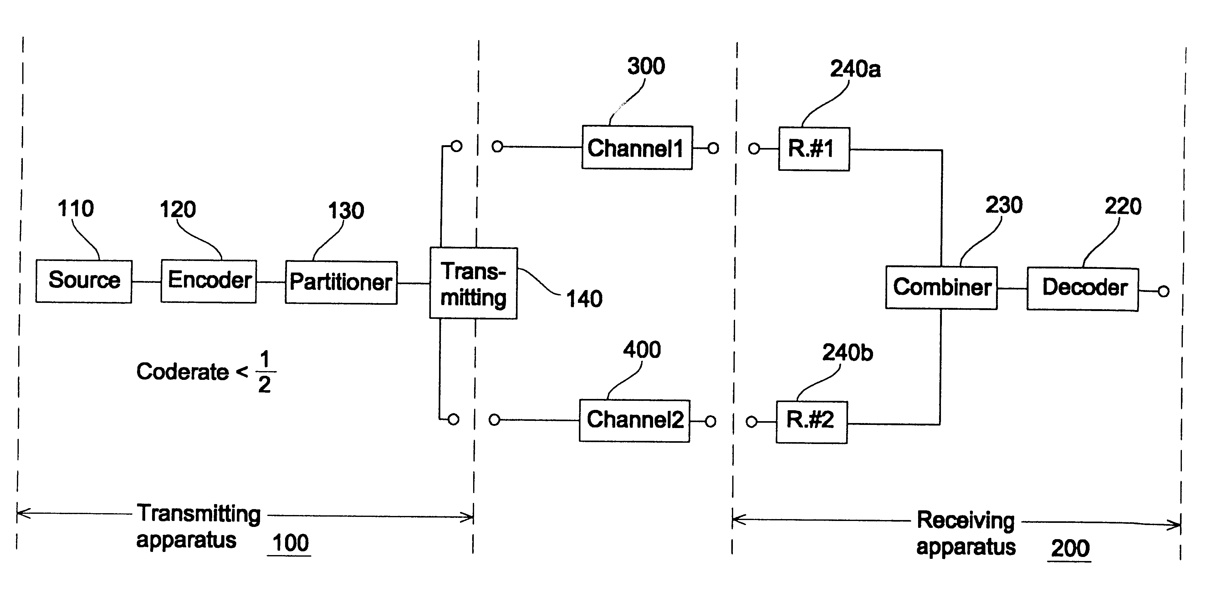
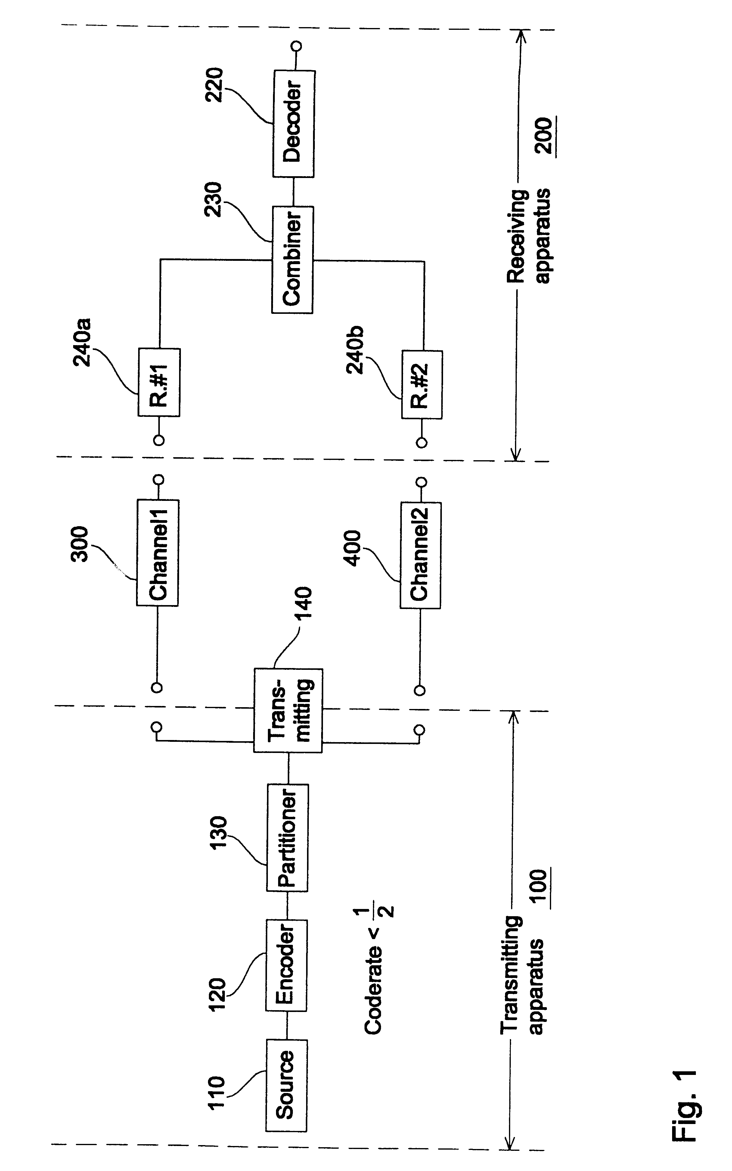
In FIG. 1 a general block diagram of an inventive apparatus for transmitting 100 and an inventive apparatus for receiving 200 is illustrated. The transmitting apparatus 100 comprises a bitstream source 110, a redundancy adding encoder 120 and a partitioner 130. The bitstream source 110 may be an MPEG encoder as described above. The encoder 120 is generally a redundancy adding encoder for generating an encoded bitstream on its output, wherein the encoder 120 is arranged to output, for a first number of input bits, a second number of output bits, the second number of output bits having at least twice as many output bits as the first number of input bits. This means that the encoder 120 implements a code rate equal to or less than 1 / 2. As it is known in the art, the code rate is defined by the number of input bits divided by the number of output bits produced by the encoder based on the number of input bits. In other words, a code rate 1 / 2 means that for each input bit, two output bits...


PUM


Abstract

An apparatus for transmitting information comprises a bitstream source for providing a bitstream representing the information, a redundancy adding encoder for generating an encoded bitstream, which is arranged to output, for a first number of input bits, a second number of output bits, the second number of output bits having at least twice as many output bits as the first number of input bits, wherein the second number of output bits includes two portions of output bits, each portion of output bits individually allowing the retrieval of information represented by the first number of input bits, and the first portion of output bits being coded based on the bitstream in a different way with respect to the second portion of output bits. The apparatus further comprises a partitioner for partitioning the second number of output bits into the two portions of output bits and a transmitter for transmitting the output bits of the first portion via a first channel and the output bits of the second portion via a second channel, the second channel being spatially different from the first channel. An inventive receiving apparatus combines the signals received via the first and second channels and uses both channel signals for channel decoding by removing redundancy. Thus, the transmitting receiving system is suitable for providing time and/or space diversity and, in the optimal case, provides a C/N value which is greater than 4.3 dB with respect to a two-channel system comprising a duplicator in the transmitter and a channel-controlled switch in the receiver.

Description

The present invention relates to concepts for digital broadcasting and, in particular, concepts for digital broadcasting suited for fading channels for wireless communication.Satellite-based broadcasting systems provide an adequate communication link only in rural areas, in which only a small number of e.g. bridges exist. Additionally, rural areas usually do not have skyscrapers. Skyscrapers as well as bridges or, generally, densly built-up areas are obstacles to satellite-based communication systems, since carrier frequencies used for such communication links involve that a channel between a sender, e.g., a satellite, and a receiver, i. e. a mobile or stationary receiver, is characterised by the line of visual contact (line of sight) between the sender and the receiver. If a skyscraper comes into the line of visual contact, i.e., the transmission channel between the satellite and the receiver, which may be positioned in a car, the received signal power will decrease substantially.G...

Claims


Application Information

Patent Timeline
IPC IPC(8): H04B7/04H04L1/02H04B7/06H04L1/06H04B7/08H04L1/00H03M13/23H04H20/00
CPCH04B7/0604H04B7/0671H04L1/0059H04L1/0068H04L1/06H04B7/0894
Inventor EBERLEIN, ERNSTBREILING, MARCOSTOESSEL, JANGERHAUSER, HEINZ
Owner FRAUNHOFER GESELLSCHAFT ZUR FOERDERUNG DER ANGEWANDTEN FORSCHUNG EV
Why Eureka
Try Eureka