Resistor for audio equipment

a technology for resistors and audio equipment, applied in the direction of resistor details, resistors, resistor enclosures/enclosements/embeddings, etc., can solve the problems of large degradation of sound quality, variation in electrical characteristics of resistance films, and high risk of magnetism giving rise to phase distortion of signals applied to resistors

Inactive Publication Date: 2001-11-13
TAKMAN ELECTRONICS
View PDF12 Cites 13 Cited by
  • Summary
  • Abstract
  • Description
  • Claims
  • Application Information

AI Technical Summary

Benefits of technology

is to provide a resistor for audio equipment that is able to prevent audio replay containing unusual sound quality caused by the effect on the characteristics of a resistance film caused by the resistor sheath becoming charged by electrostatic induction.

Problems solved by technology

Even slight variations in the electrical characteristics of the resistors used in high-fidelity amplifiers result in a major degradation of the sound quality.
When this happens, there is a high possibility of the charge carriers causing variation in the electrical characteristics of the resistance film.
Moreover, when a magnetic sheathing is used, there is a high risk of the magnetism giving rise to phase distortion of signals applied to the resistor.
However, with the shielding and resistance film being formed integrally with the resistor carrier, the signal flowing through the resistance film charges the resistor carrier, which can adversely affect signals applied to the resistor.
That is, the sheathing is in direct contact with the resistance film and therefore is charged by electrostatic induction, thereby affecting signals applied to the resistance film.
With this configuration, the fact that the resistance film is formed on the resistor surface facing the conductive film on the sheath side, with a space therebetween, makes it more difficult for the resistance film to be subjected to the effects of extraneous electrostatic induction.
However, the charge produced in the insulation slit by the electrostatic induction and the charge produced by signals applied to the conductive film will cancel each other out.

Method used


Image

  • Resistor for audio equipment
  • Resistor for audio equipment
  • Resistor for audio equipment

Examples


first embodiment

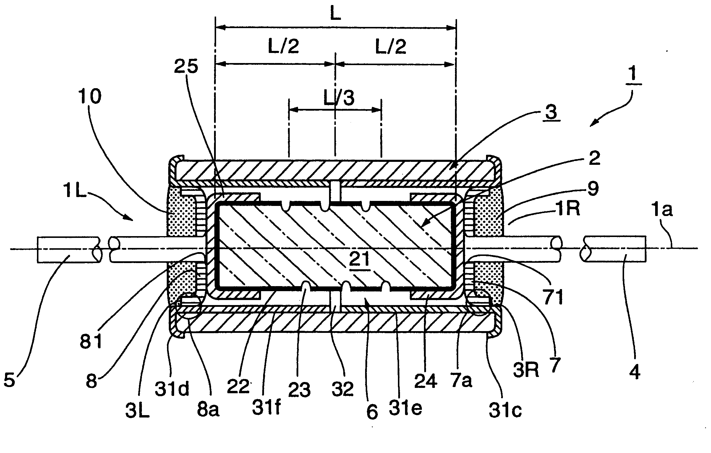
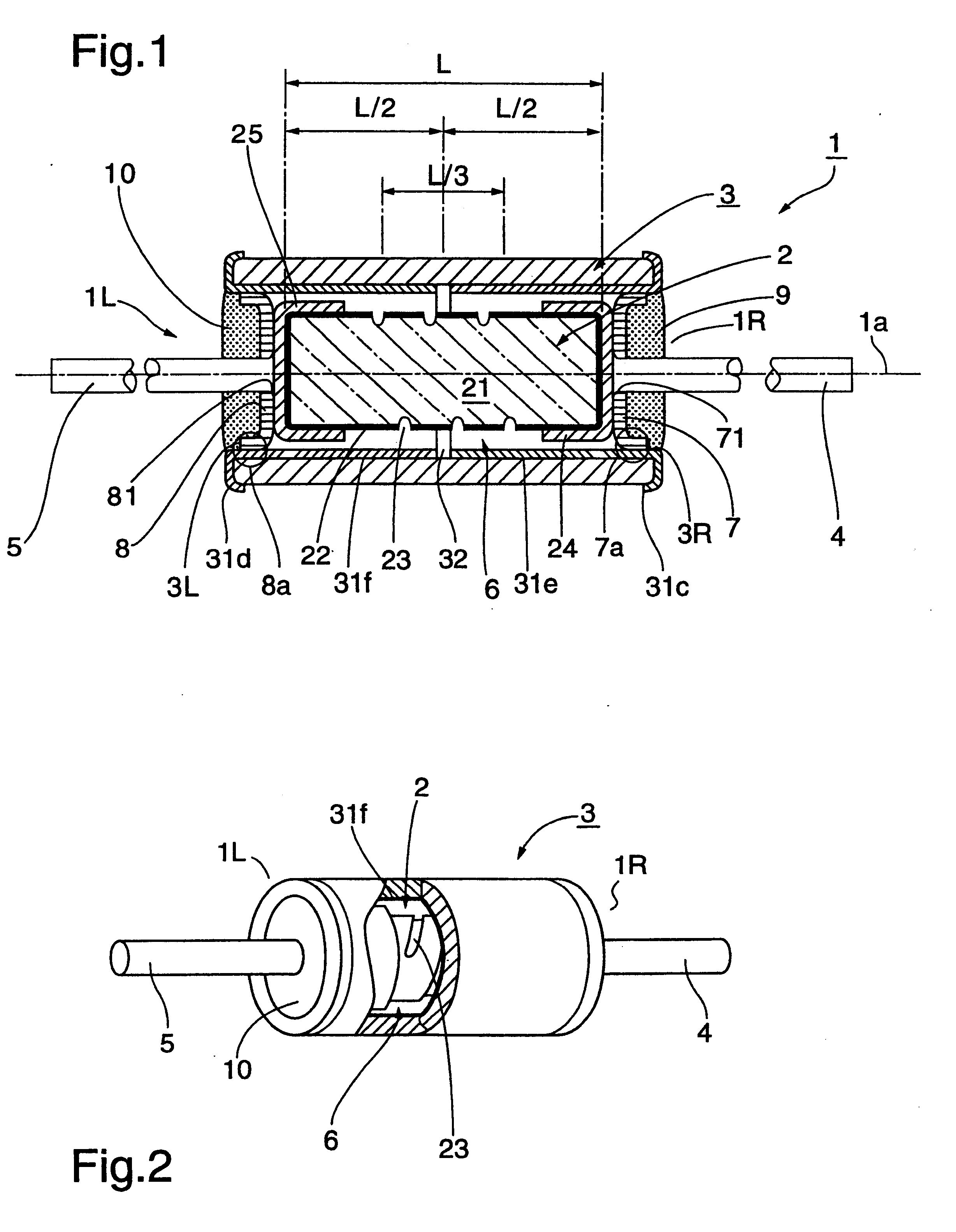
FIGS. 1 to 4 show the resistor according to the invention. As shown by the drawings, a resistor 1 for audio equipment comprises a cylindrical resistor body 2, a tubular sheath 3 that covers the resistor body 2, a first lead wire 4 extending from a resistor first end 1R along axis 1a, and a second lead wire 5 extending from a resistor second end 1L along axis 1a. A space 6 having an annular section is formed between the resistor body 2 and the sheath 3.

The resistor body 2 includes a cylindrical ceramic substrate 21. A resistance film 22 of a prescribed thickness is formed over the whole of the surface of the substrate 21. The resistance film 22 is comprised of carbon, nickel-chrome, tin oxide or the like, and can be formed by a coating method such as pyrolysis, sputtering, plating and the like. A spiral groove 23 having a constant width is formed in the resistance film, exposing the substrate surface. The groove 23 is used to adjust the resistance of the resistor 1.

A cap electrode of...

second example

FIG. 5 is a diagram showing a longitudinal cross-sectional view of a leadless resistor according to a second embodiment of the invention. Except for the fact that the resistor 100 of this example is leadless, the basic configuration is the same as that of the first embodiment. Therefore, with reference to FIG. 5, identical parts have been given the same reference numbers or symbols, and only different parts will be described here.

With respect to the resistor 100, internal electrodes 101, 102, made of conductive material, are attached to end portions 2R, 2L of the resistor body 2, and over these are fitted conductive cap electrodes 24 and 25. Cap electrode plates 7A and 8A do not have through-holes for leads. Annular external electrodes 103 and 104, formed of conductive material, are affixed at the ends of the sheath 3, over the annular end faces and outer peripheral portions. The external electrodes 103 and 104 have electrical continuity with the conductive film 31 covering the surf...


PUM


Abstract

A resistor 1 is used in high-fidelity amplifiers for audio equipment. The resistor 1 includes a cylindrical resistor body 2, a tubular sheath 3 into which the resistor body 2 is coaxially inserted, and a conductive film portion 31a formed on the inside surface 3a of the sheath 3. The conductive film portion 31a faces to a resistance film 22 covering the surface of the resistor body 2 with an annular space 6. An insulating slit 32 is formed at a central point along the resistor axis 1a, separating the conductive film 31 into left and right parts that are electrically isolated from each other. The sheath covering the resistor body 2 prevents distortion of signals in the resistance film 22 caused by extraneous electrostatic induction charges.

Description

1. Field of the InventionThis invention relates to a resistor for audio equipment adapted for use in a high-fidelity amplifier in audio equipment.2. Prior Art DescriptionIn audio equipment, a high-fidelity amplifier is used to amplify the low level signals and reproduce sounds with good quality. Even slight variations in the electrical characteristics of the resistors used in high-fidelity amplifiers result in a major degradation of the sound quality. This has given rise to proposals to suppress variations in the characteristics of resistors caused by extraneous signal noise, to prevent the amplifier circuitry from being adversely affected.JP-A 61-34901, for example, discloses an induction array of resistors for audio equipment applications in which, in order to improve the quality of reproduced sound, the induction field generated when electricity passes through the resistance film is utilized to minimize distortion with respect to the signal current.In another example, JP-A 3-2884...

Claims


Application Information

Patent Timeline
Patent Type & Authority Patents(United States)
IPC IPC(8): H01C1/06H01C7/00
CPCH01C1/06
Inventor ORII, TAIKO
Owner TAKMAN ELECTRONICS
Why Eureka
Try Eureka