System for and a method of compensating polarization dispersion in an optical transmission system

Inactive Publication Date: 2001-11-13
ALCATEL LUCENT SAS
View PDF5 Cites 22 Cited by
  • Summary
  • Abstract
  • Description
  • Claims
  • Application Information

AI Technical Summary

Benefits of technology

Thus, the compensation to be applied is determined without regard to the inherently random nature of PMD, but the proposed solution allows for this random aspect by improving the tolerance of the system to chromatic dispersion.
The invention also provides a compensation method corresponding to the system defined above. This method applies a first stag

Problems solved by technology

The performance of an optical transmission system, in particular in terms of signal quality and bit rate, is limited in particular by optical properties of the link, which is subject to physical phenomena which degrade the optical signals.
In reality, the optimum of exact compensation of chromatic dispersion is never achieved because the quality of the compensated signal received also depends on other transmission parameters, in particular the type of modulation of the transmitted signal.
This distortion is due to birefringence of the fiber, which depolarizes the optical signal during transmission.
The distortion of the pulses received by the

Method used


Image

  • System for and a method of compensating polarization dispersion in an optical transmission system
  • System for and a method of compensating polarization dispersion in an optical transmission system
  • System for and a method of compensating polarization dispersion in an optical transmission system

Examples


Example

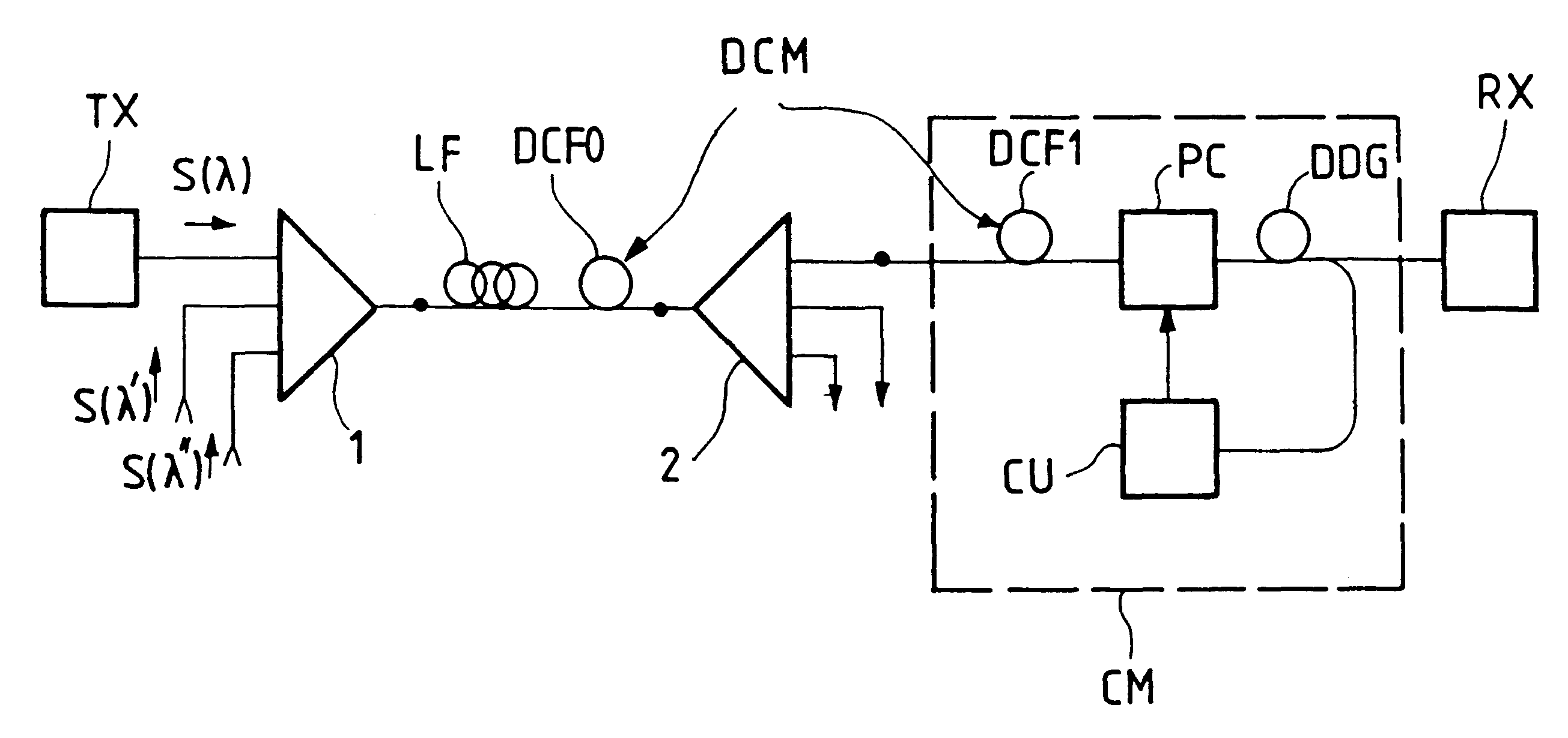
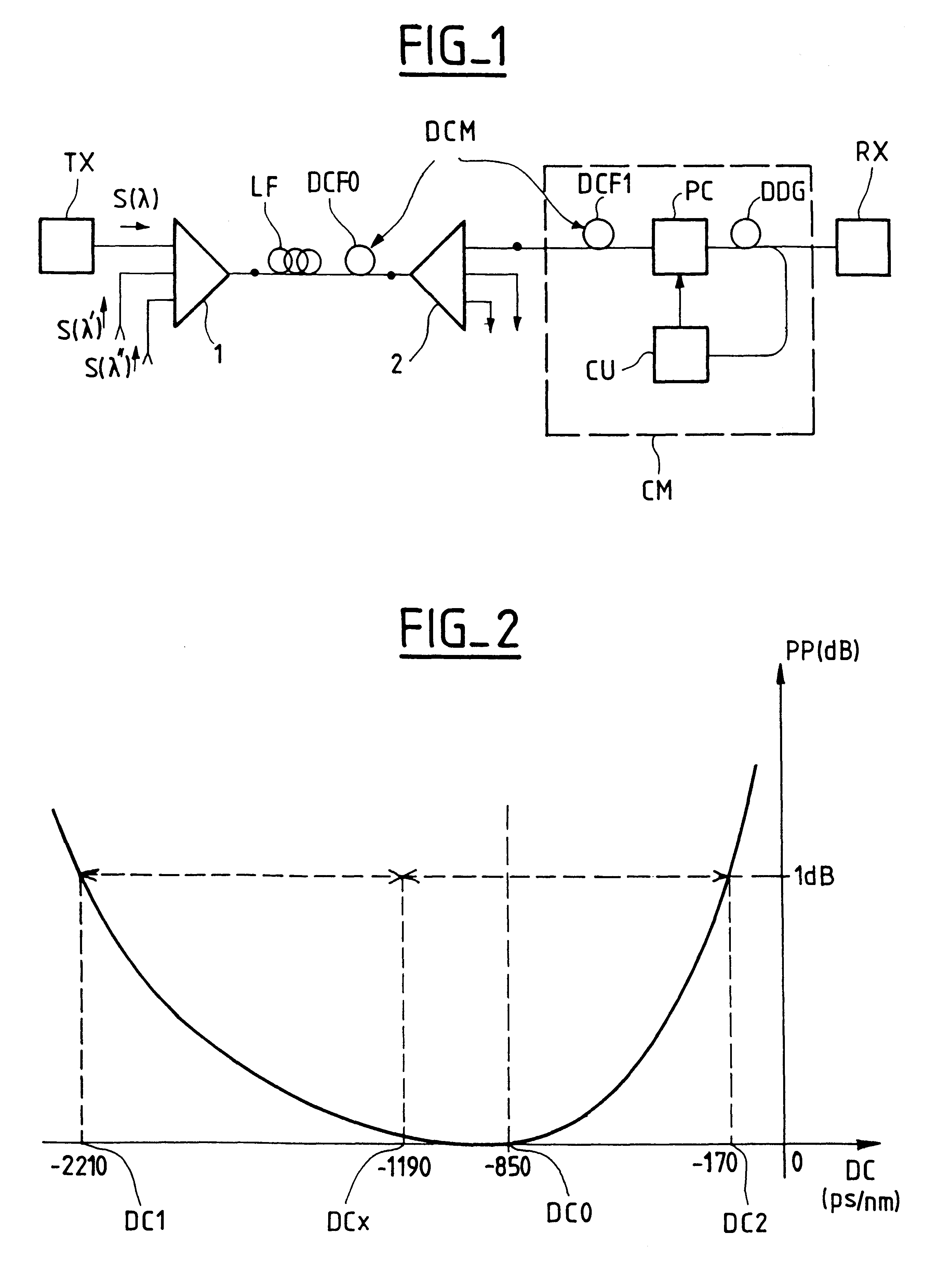
FIG. 1 is a block diagram of one example of an optical transmission system including a compensator system according to the invention.

The system shown by way of example is a wavelength division multiplex system in which a plurality of channels S.lambda., S.lambda.', S.lambda." have respective carrier wavelengths .lambda., .lambda.', .lambda.". Each channel, for example channel S.lambda., originates at a transmitter terminal TX which outputs an optical signal taking the form of an amplitude (and / or optical frequency) modulated polarized carrier wave. The channels are combined in a multiplexer 1 whose output is connected to an optical transmission link. The link typically includes an optical fiber LF and can include optical amplifiers (not shown) at the upstream and / or downstream end of the fiber. The link can equally include a plurality of fiber sections with optical amplifiers between them.

The end of the link is connected to a receiver terminal RX via a demultiplexer 2 whose function...


PUM


Abstract

To increase the bit rate and distance of transmission of data by optical fiber, the system compensates polarization dispersion of the link by means of a polarization controller, a differential delay generator for generating a differential delay between two orthogonal polarization modes and a control unit for the polarization controller. It further includes a chromatic dispersion compensator inserted in the link and which applies a fixed value of compensation which minimizes the error rate of the signals received after transmission. Application to long-haul optical transmission via standard fibers.

Description

The field of the invention is that of transmitting signals by optical means and more particularly transmission at high bit rates on long-haul links using optical fibers.The invention concerns a system for dynamically compensating at least some of the polarization dispersion observed in fiber optic transmission systems.A fiber optic transmission system typically includes:a transmitter terminal modulating the optical frequency and / or power of at least one optical carrier wave as a function of the information to be transmitted,an optical transmission link consisting of at least one monomode fiber section conveying the signal output by the transmitter terminal, anda receiver terminal receiving the optical signal transmitted via the fiber.The performance of an optical transmission system, in particular in terms of signal quality and bit rate, is limited in particular by optical properties of the link, which is subject to physical phenomena which degrade the optical signals. Of all the ph...

Claims


Application Information

Patent Timeline
IPC IPC(8): H04B10/18H04B10/2507H04B10/2525H04J14/00H04J14/02
CPCH04B10/2525H04B10/2572H04B2210/252
Inventor PENNINCKX, DENISROY, FABIEN
Owner ALCATEL LUCENT SAS
Why Eureka
Try Eureka