Brake-by-wire system having conditioned brake boost termination at key off

Inactive Publication Date: 2001-12-04
FORD GLOBAL TECH LLC
View PDF9 Cites 12 Cited by
  • Summary
  • Abstract
  • Description
  • Claims
  • Application Information

AI Technical Summary

Problems solved by technology

However, turning the ignition switch off to de-energize those circuits may remove power from devices that when powered, aid in reducing the pedal effort required to apply the brakes via the master cylinder.
Hence, brake pedal effort may increase significantly when the ignition switch is turned off.

Method used


Image

  • Brake-by-wire system having conditioned brake boost termination at key off
  • Brake-by-wire system having conditioned brake boost termination at key off
  • Brake-by-wire system having conditioned brake boost termination at key off

Examples


Embodiment Construction

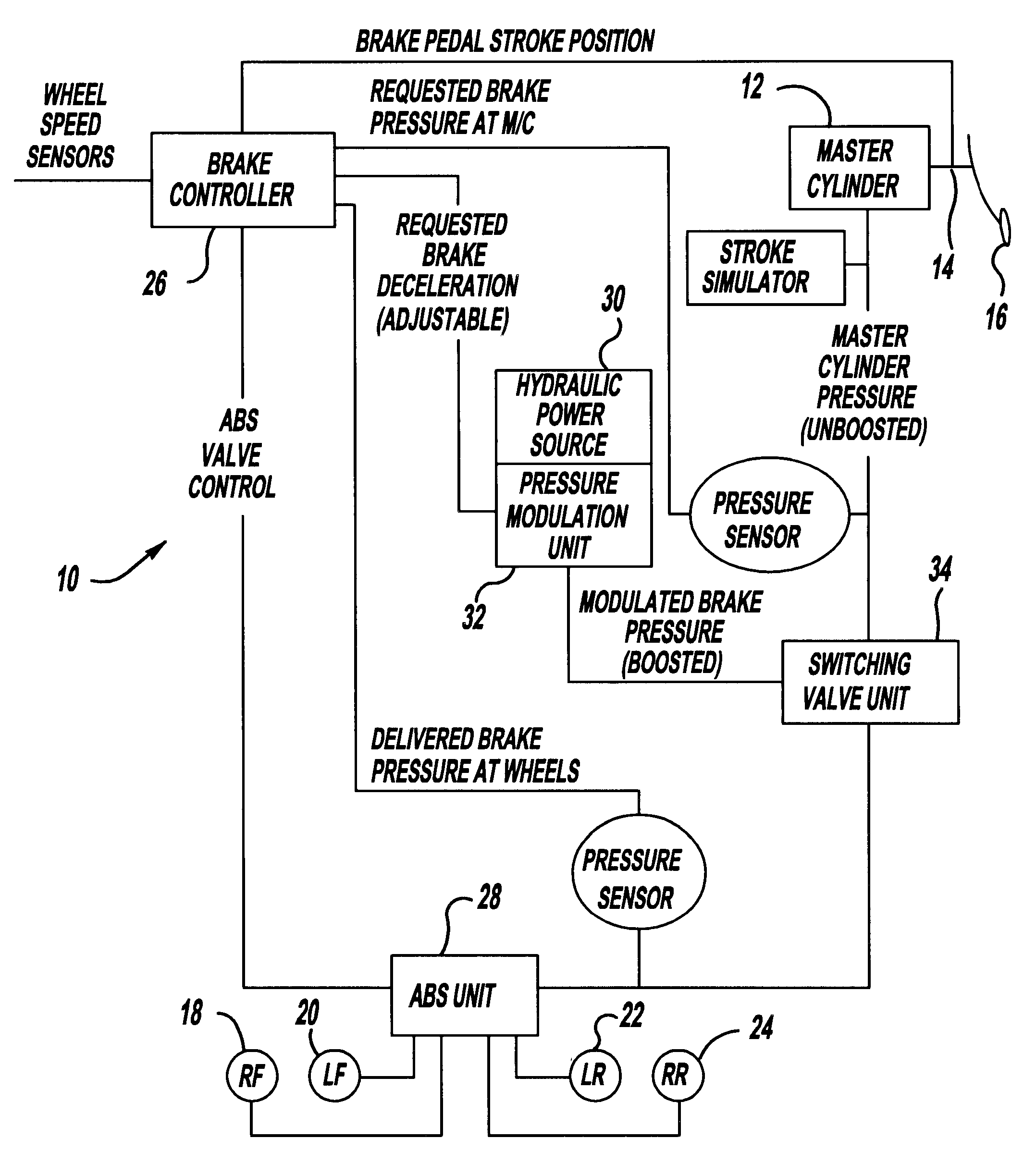
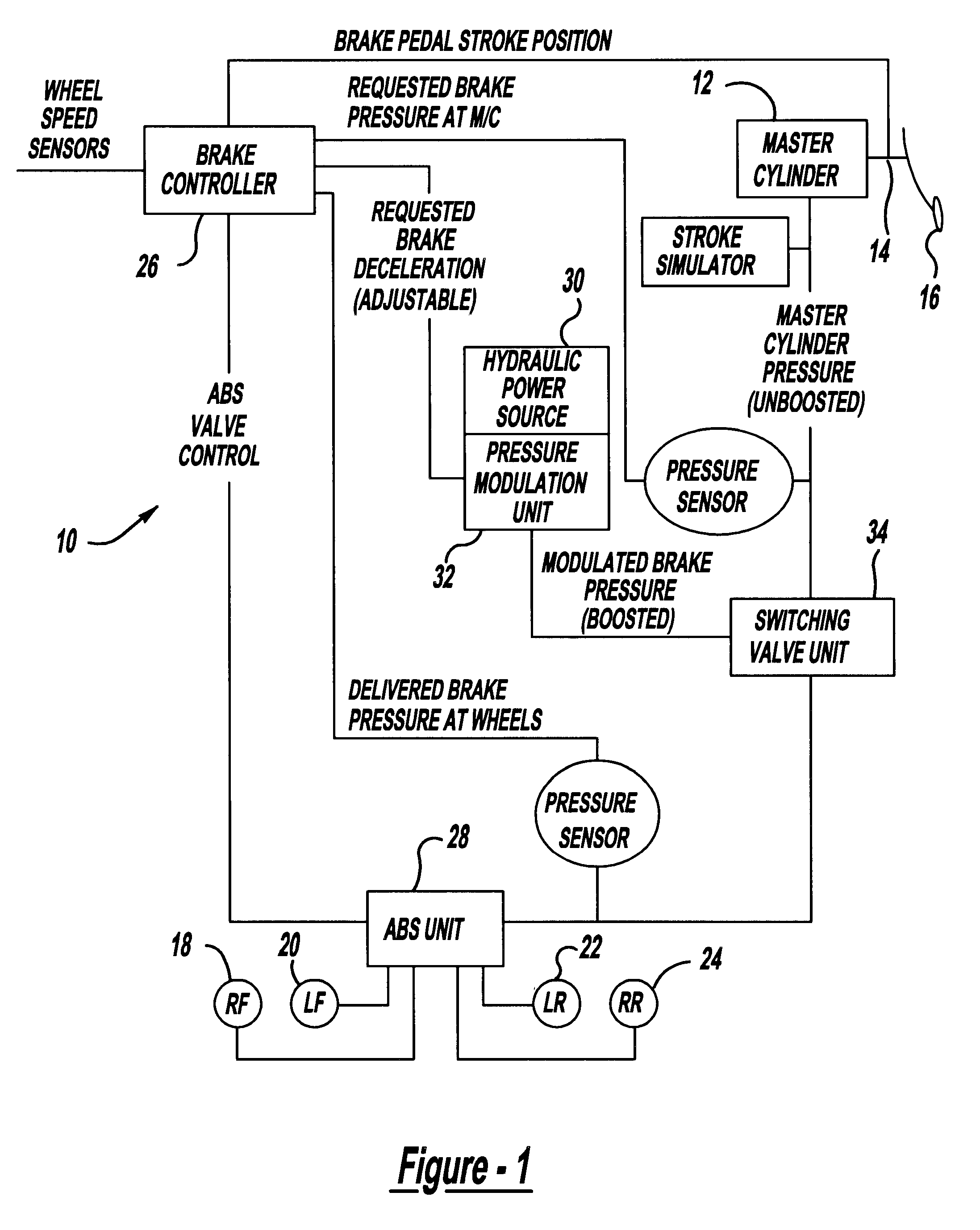
FIG. 1 shows a representative brake-by-wire system comprising a hydraulic brake master cylinder 12 having a plunger 14 which is adapted to be depressed by operation of a brake pedal 16 to brake road-engaging wheels of a motor vehicle. Braking may be accomplished either by hydraulic brakes at individual wheels, such as 18, 20, 22, 24, or by regenerative braking, as determined by an electronic brake controller 26. Hydraulic braking is applied through an ABS unit 28. Boost for aiding hydraulic braking so as to reduce pedal effort that would otherwise be required is derived from a hydraulic power source 30 whose pressure is modulated by a pressure modulation unit 32 under the control of brake controller 26. For developing the proper modulation, controller 26 senses brake pedal input with the use of one or more of the following: stroke position sensor; master cylinder pressure sensor; or any other sensor that may be used to indicate pedal input.

FIG. 1 includes a back-up hydraulic circuit...


PUM


Abstract

An electric powered brake system (10) for braking road-engaging wheels of a motor vehicle. An ignition switch for turning a motor of the vehicle on and off also controls the application of electric power to the electric powered brake system. A control and method (FIGS. 2 and 3) for maintaining application of full electric power to the electric powered brake system when the ignition switch is operated from ON to OFF so long as at least one parameter (60, 62, 64, 66) related to a respective component of the vehicle and indicative of a need to maintain full electric power application to the brake system continues to exist and for discontinuing application of full electric power to the brake system when all of selected ones of several such parameters are indicative of lack of need to maintain full electric power application to the brake system.

Description

1. Field of the InventionThis invention relates generally to brake systems for wheeled motor vehicles, and more specifically it relates to a brake-by-wire system.2. Background InformationA brake-by-wire system may comprise a pedal that depresses a master cylinder plunger to perform the service brake function for a motor vehicle. The service brake function is performed by selectively applying electrically boosted hydraulic brakes or regenerative brakes. Hydraulic brakes generally apply friction forces to the wheels to dissipate energy as heat. Regenerative brakes may take any of various forms, but are often considered to comprise a rotary electric machine load that is applied to one or more driven wheels. When a regenerative brake is applied, energy flows from the wheels to operate the electric machine as a generator that converts the energy into electricity. The electricity is often used to charge an energy storage device, such as a battery. Whether hydraulic or regenerative brakes ...

Claims


Application Information

Patent Timeline
IPC IPC(8): B60T8/40B60T13/74B60T13/00B60T13/66
CPCB60T8/4072B60T13/662B60T13/741
Inventor CURRAN, PATRICK JOSEPHCROMBEZ, DALE SCOTTNAPIER, STEVEN LEE
Owner FORD GLOBAL TECH LLC
Why Eureka
Try Eureka