Disk striping method and storage subsystem using same

a technology of storage subsystems and disks, applied in the direction of instruments, input/output to record carriers, computing, etc., can solve the problems of high data transfer rates, and high data transfer rates to be sustained for extended periods

Inactive Publication Date: 2001-12-04
AVAGO TECH INT SALES PTE LTD
View PDF1 Cites 71 Cited by
  • Summary
  • Abstract
  • Description
  • Claims
  • Application Information

AI Technical Summary

Benefits of technology

It is therefore an object of the present invention to provide methods and associated structures for mapping striped data within a storage subsystem for improving both disk performance and disk utilization.
It is a further object of the present invention to provide methods and associated structures for mapping striped data within a storage subsystem for improving both disk performance and disk utilization by distributing the data in a stripe over some outer zones and some inner zones.
It is therefore an object of the present invention to provide methods and associated structures for mapping striped data within a storage subsystem for improving both disk performance and disk utilization by assuring that all stripes in the storage subsystem are capable of sustaining approximately average performance of the inner and outer zones of the disks.
It is therefore an object of the present invention to provide methods and associated structures for mapping striped data within a disk array storage subsystem for improving both disk performance and disk utilization by mapping sequential blocks on half the disks in the array from innermost to outermost zones and on half the disks in the array from outermost to innermost zones.

Problems solved by technology

Further, such applications often require high performance levels for the storage subsystems.
For example, the capture of video data for storage on a disk storage subsystem often requires very high data transfer rates to store the captured data and requires that such high data transfer rates be sustained for extended periods of time.
Where the volume of such data increases and reliance on computer systems to store and manipulate such data increases, disk performance and disk utilization are constant and continuing challenges.
As noted above, inner portions of the disk may provide slower performance than outer portions due to physical geometry and storage density of the disks.
Although striping of multiple disks enhances performance, it diminishes reliability.
Striping diminishes reliability because failure of any one of the disks is equivalent to the failure of the entire array.
For example, real time image capture or high speed data acquisition must store captured data as quickly as it is generated or risk loss of data.
Such applications may be wasting the higher performance capability of the array where outer zones happen to be in use but must do so to sustain a minimum performance level experienced within inner zones.
However, such solutions may be wasteful of storage capacity where the size of individual disk drives cannot be effectively tailored to meet the requirements of the application.
Though such a goal may be achieved in certain physical zone layouts of particular disk drives, such a goal may not be universally achievable on all disk drives.
Therefore, complex rapid search techniques provide little or no added benefit as compared to their added complexity in processing each I / O request.
However, the segment address is not relevant in this computational algorithm because the region table contains enough information about stripes and stripe sizes that the disk and disk address can be derived without a segment mapping.
Where less data is so pre-computed, the table requires less storage space at the cost of computational complexity associated with processing of each I / O request.

Method used


Image

  • Disk striping method and storage subsystem using same
  • Disk striping method and storage subsystem using same
  • Disk striping method and storage subsystem using same

Examples


Embodiment Construction

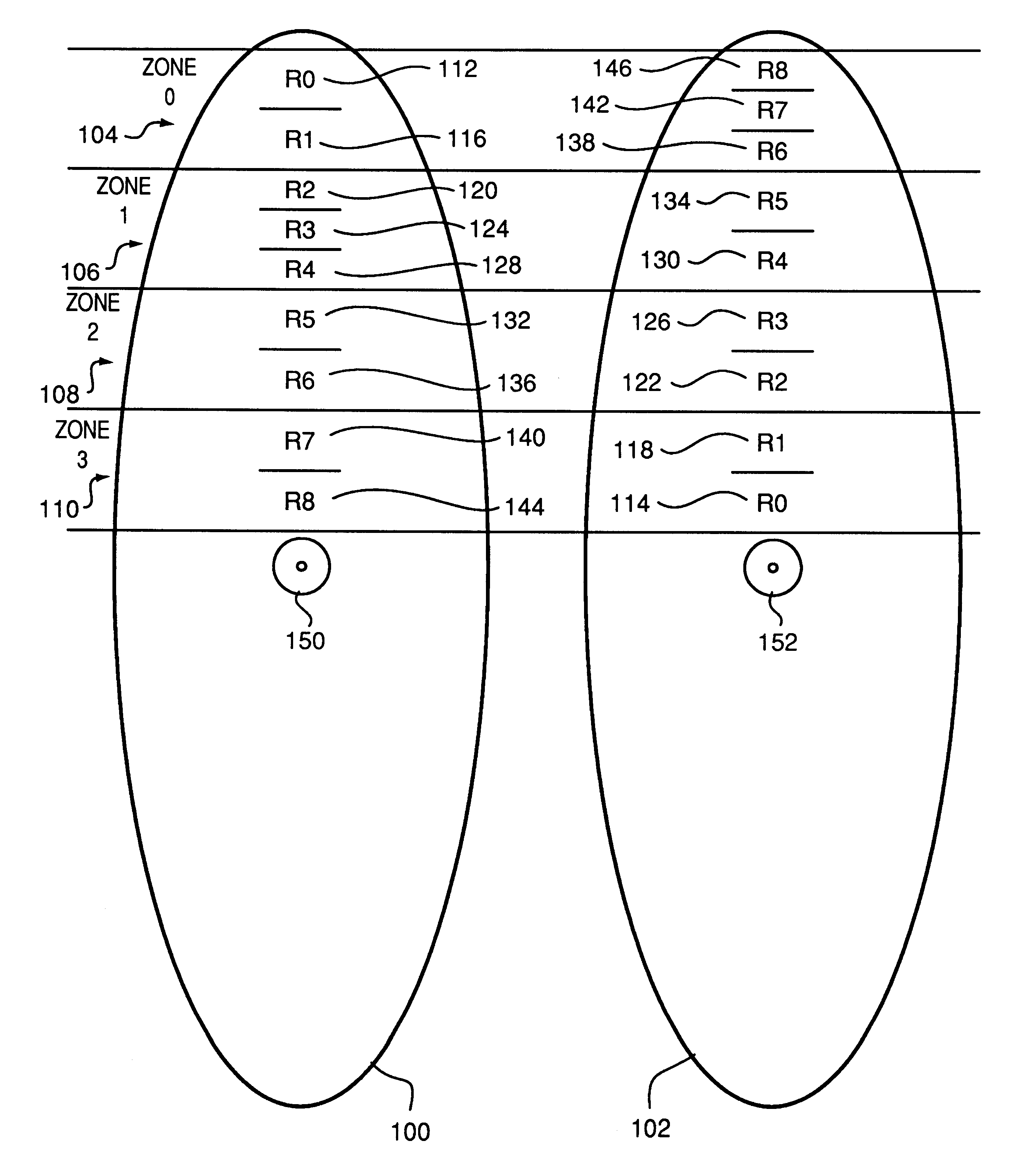
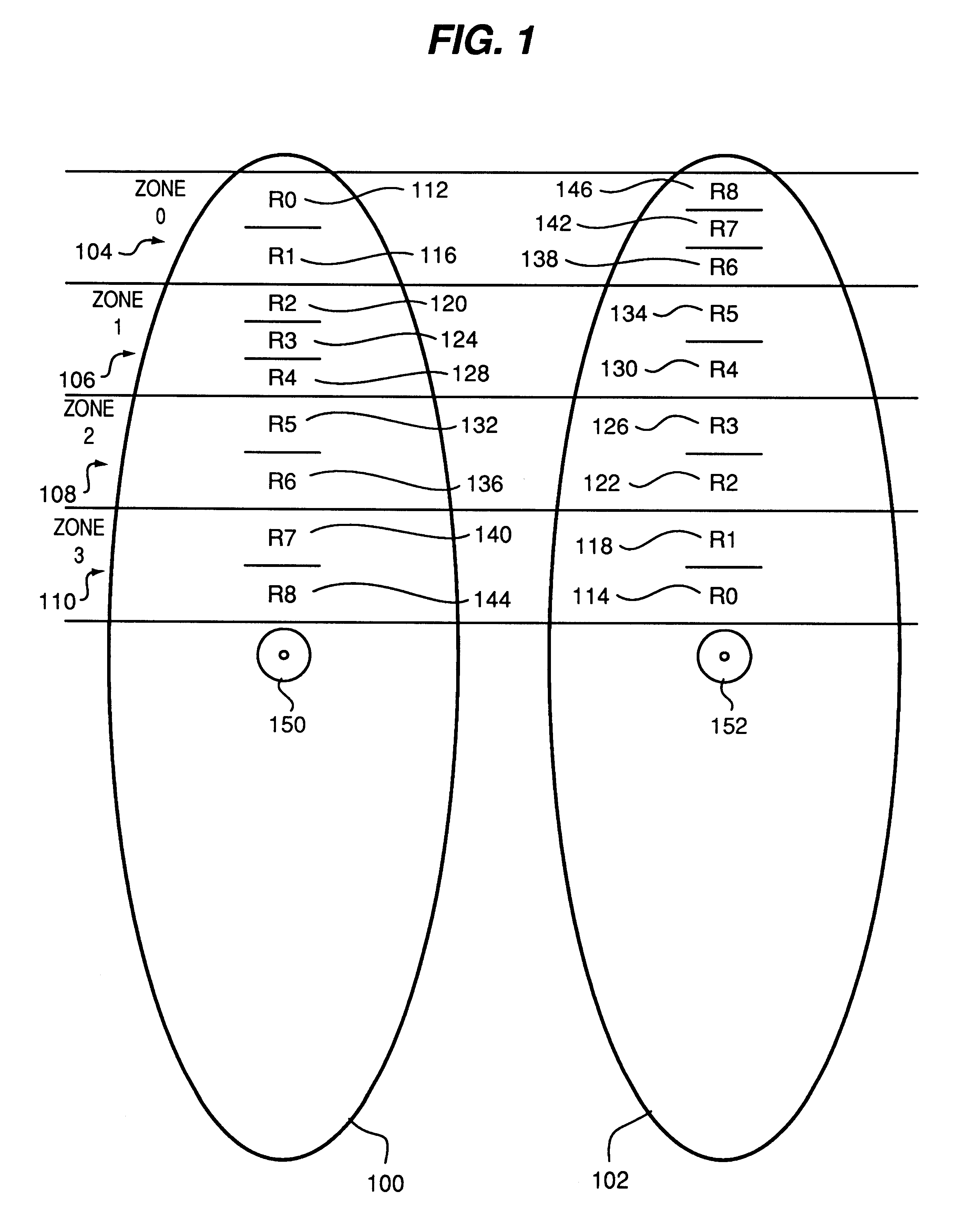
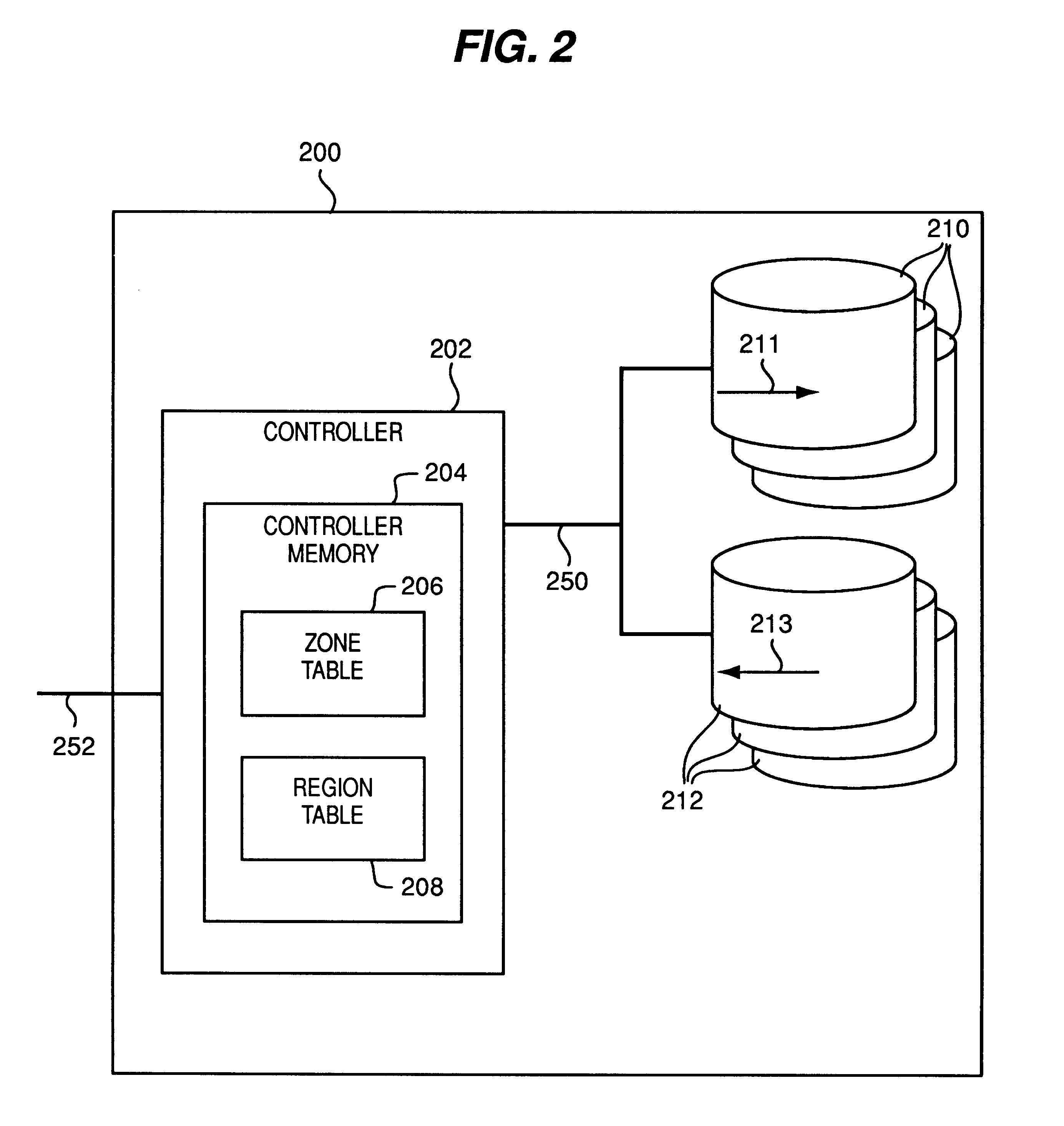
FIG. 8 is a block diagram depicting alternate embodiments of the structures and methods of the present invention. Specifically, FIG. 8 shows a single disk drive (a disk spindle) 700 having multiple, independently operable actuators 708 and 710 manipulating information on storage medium 704. Since the actuators 708 and 710 are independently operable, one actuator 708 is operable to map sequential locations from outer zones to inner zones as indicated by inward arrow 716. The second actuator is operable to map sequential locations on the disk spindle from inner zones to outer zones as indicated by outward arrow 718. Each actuator 708 and 710 may be independently operable manipulating regions in different zones. The regions are therefore used in a striped fashion as described herein above to permit simultaneous I / 0 operation through two (or more) actuators.

Such an embodiment achieves similar goals of improving consistency of performance by combining higher performance regions with lowe...


PUM


Abstract

Methods and systems for mapping logical disk addresses to physical locations so as to achieve consistent sustained performance for a striped disk array I / O subsystem. Stripes (regions) are defined by a region mapping table. Zones are defined by the disk manufacturer as groups of cylinders having identical number of sectors per track. Outer zones store more data and therefore provide a higher level of sustained performance as compared to inner zones. Substantially half the disks in the array are mapped such that logical sequential blocks are allocated from outer most, higher performance, zones to inner, lower performance, zones. The other half of the drives in the array are mapped from inner zones to outer zones. Each region (stripe) therefore includes a mix of higher performance zones and lower performance zones. Each region therefore provides more consistent sustained performance as compared to prior techniques. Improved consistency in performance enables better utilization of storage system performance and storage capacity as compared to prior techniques. Alternate embodiments of the invention provide for striping such regions using multiple actuators within a single drive spindle and for providing such mapping functions within low level drive control electronics.

Description

1. Field of the InventionThis invention relates to data storage subsystems and, more particularly, to a disk striping method operable within a storage subsystem for improving both performance and storage capacity utilization.2. Discussion of Related ArtStorage systems provide persistent storage of information for computer systems. These storage systems often integrate a number of data storage devices (e.g., tape drives, compact disks and hard disk drives) to store data and make it accessible to a computer system. Storage capacity requirements and performance requirements are ever increasing. For example, so-called multi-media computer applications require storage of vast quantities of audio and video data. Further, such applications often require high performance levels for the storage subsystems. For example, the capture of video data for storage on a disk storage subsystem often requires very high data transfer rates to store the captured data and requires that such high data tran...

Claims


Application Information

Patent Timeline
Patent Type & Authority Patents(United States)
IPC IPC(8): G06F3/06
CPCG06F3/0608G06F3/061G06F3/0631G06F3/0689
Inventor KIRBY, J. W.
Owner AVAGO TECH INT SALES PTE LTD
Why Eureka
Try Eureka