The fuel injection valve according to the invention, with the characterizing features of claim 1 has the
advantage over the prior art that a
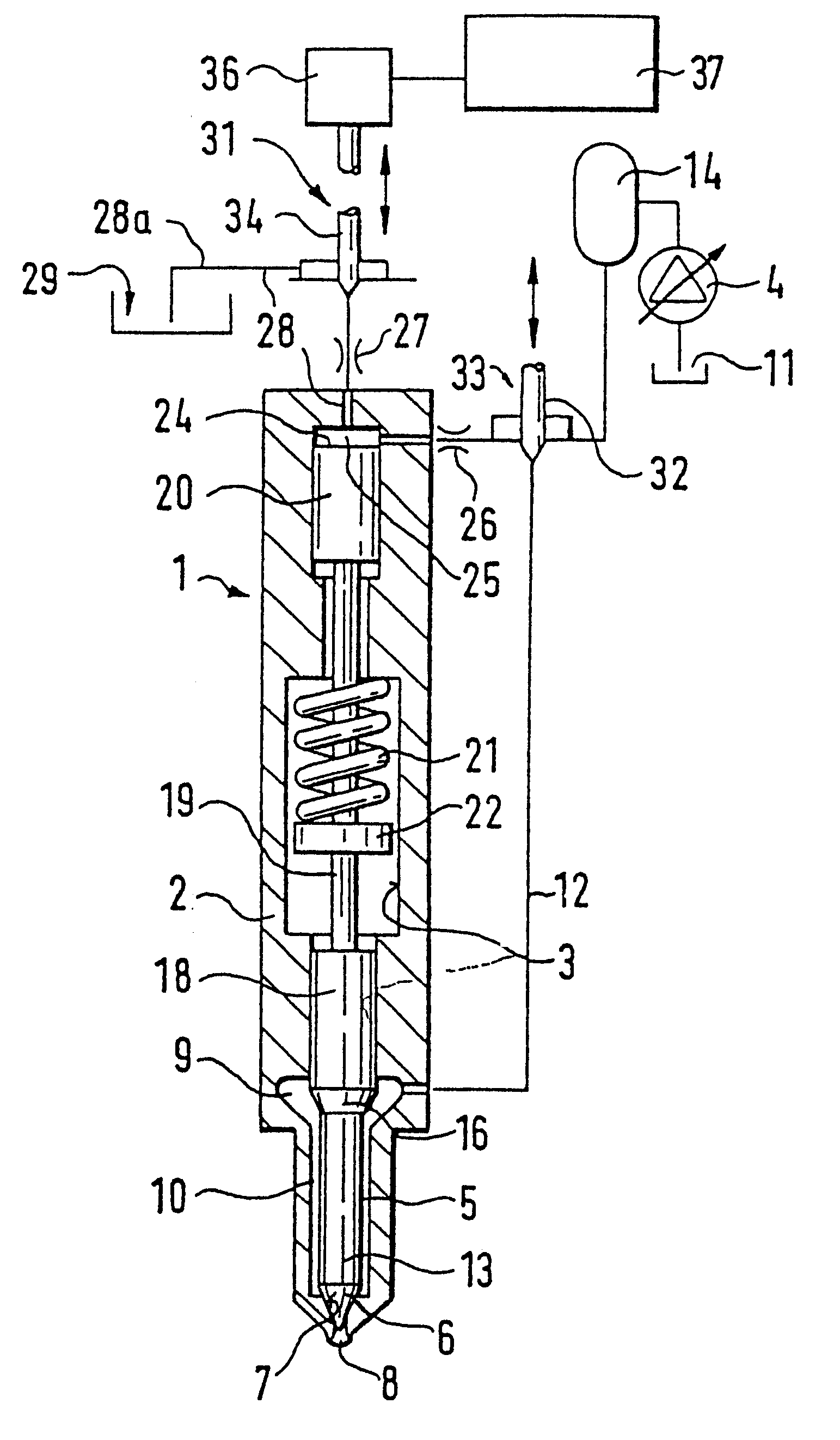
safety valve is provided, which is controlled synchronously to the control of the pressure in the control chamber and synchronously to the desired injection in such a way that there is a communication between the high-pressure fuel chamber and the pressure chamber only at the times of the actual injection to be produced. If the control of the control chamber fail due to a non-functioning control valve, or if a malfunction occurs in the fuel injection valve itself, then the duration of the supply with high-pressure fuel can be limited in this manner, wherein the safety valve does not have to be controlled with the same precision as the control valve for controlling the pressure in the control chamber, and the open state of the safety valve can also extend over the mutual time period of the pre-injection and the main injection.
According to claims 2 and 3, the control valve can be embodied either as a 3 / 2-way valve or as a 2 / 2-way valve. According to claims 4 and 5, the control valve and the safety valve are jointly actuated in an advantageous manner by means of a single actuation mechanism. According to claim 4, the safety valve can be electrically controlled or according to claim 5, it can be actuated jointly with the control valve, which reduces the structural cost of control elements. A separate control according to claim 4 produces the possibility of separately controlling both valves in the switching
rhythm.
According to claim 6, a
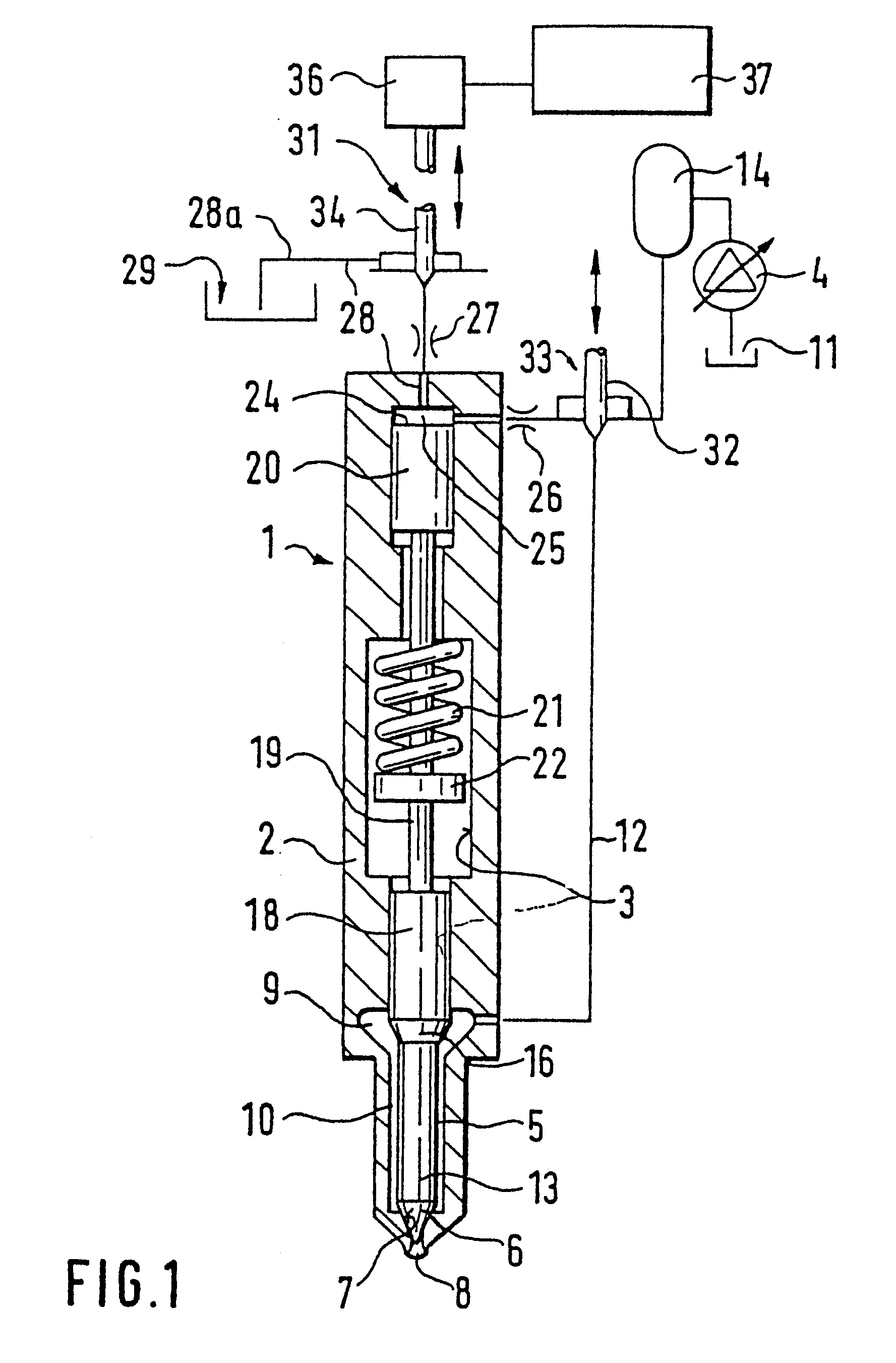
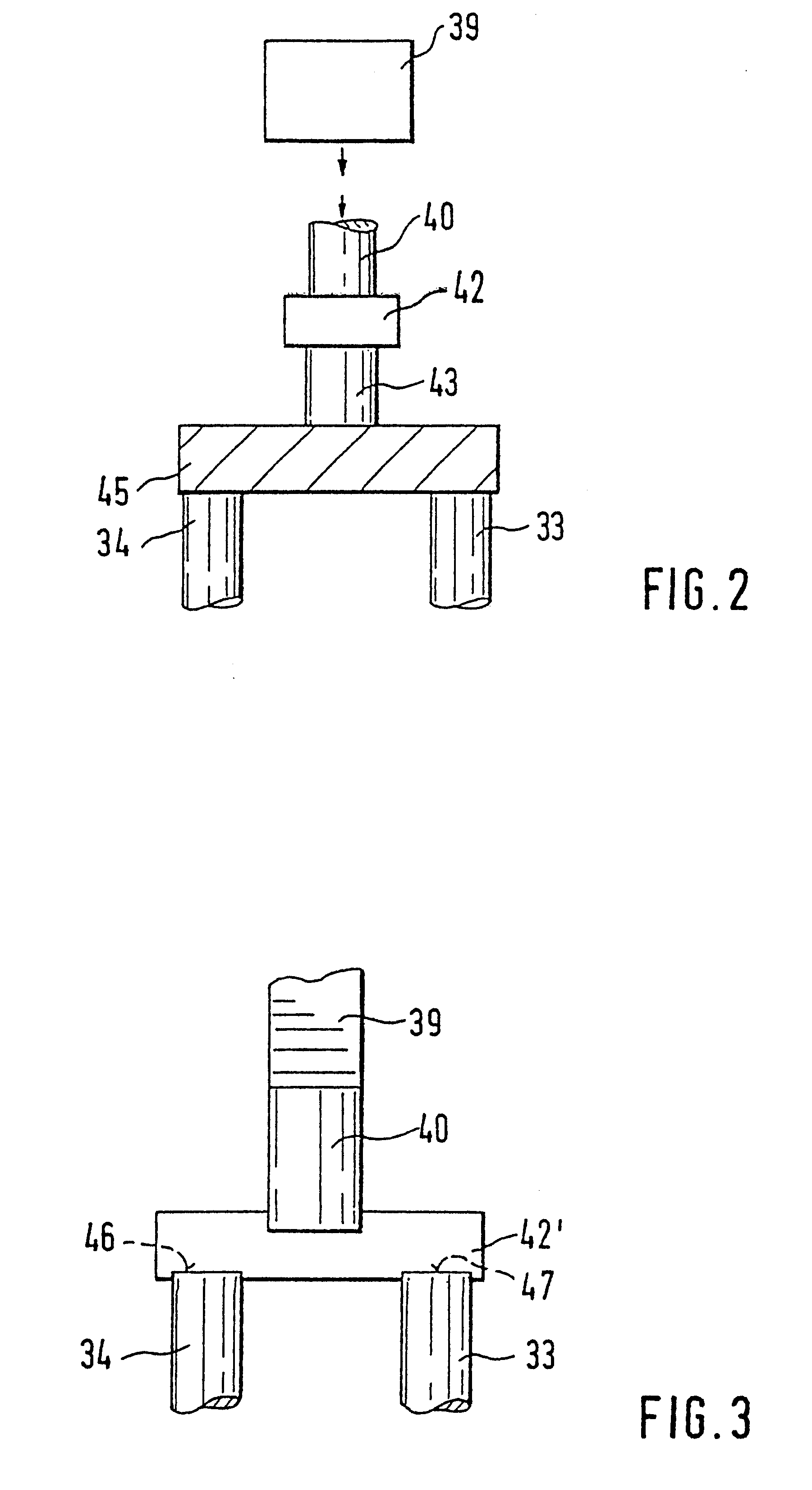
hydraulic pressure intensifier is advantageously used or, according to claim 7, a mechanical bridge is advantageously used which hydraulically transmits an actuation force to the control valve and the safety valve. According to claim 8, the hydraulic boom can be disposed between the actuation mechanism and the valve members of the control valve and the safety valve. The valve springs of these two valves can be embodied either as open when the actuation mechanism is triggered, or, in an alternative to this, as closed when it is triggered. According to claim 11, a very advantageous embodiment is comprised in that the safety valve is controlled as a function of the pressure in the control chamber. This permits a
cost savings in the actuation of the two valves, the control valve and the safety valve. According to claim 19, a further advantageous improvement of the invention is comprised in that the valve member controls two valve seats with its valve body, wherein with the passage of the valve body from one
valve seat to the other, a momentary relief of the control chamber occurs, which results in a very short injection. In a further embodiment according to claim 20, the safety valve can be embodied as a 3 / 2-way valve and in its one position, can produce the communication between the high-pressure fuel reservoir and the control chamber, which with interrupted relief of the control chamber by means of the control valve, signifies a closing of the fuel injection valve member and at the same time, prevents the communication between the high-pressure fuel reservoir and the pressure chamber of the fuel injection valve. In its other position, this latter communication is produced and the communication to the control chamber is interrupted, which produces a rapid opening of the fuel injection valve member with the corresponding control by means of the control valve. In an advantageous embodiment according to claim 21, a piezoelectric actuation device is provided as an actuation mechanism. By means of such an actuation device, in particular very rapid switching sequences can be produced, with an extremely precise metering of the fuel injection quantity and fuel injection time. This is particularly also true in connection with claim 19 in whose embodiment a short intermediary relief of the control chamber can be achieved in order to produce a short injection. This injection is used the pre-injection before a subsequent main injection and viewed in and of itself, is a known measure for reducing
combustion noise in internal
combustion engines.
According to claim 6, a
hydraulic pressure intensifier is advantageously used or, according to claim 7, a mechanical bridge is advantageously used which hydraulically transmits an actuation force to the control valve and the safety valve. According to claim 8, the hydraulic boom can be disposed between the actuation mechanism and the valve members of the control valve and the safety valve. The valve springs of these two valves can be embodied either as open when the actuation mechanism is triggered, or, in an alternative to this, as closed when it is triggered. According to claim 11, a very advantageous embodiment is comprised in that the safety valve is controlled as a function of the pressure in the control chamber. This permits a
cost savings in the actuation of the two valves, the control valve and the safety valve. According to claim 19, a further advantageous improvement of the invention is comprised in that the valve member controls two valve seats with its valve body, wherein with the passage of the valve body from one
valve seat to the other, a momentary relief of the control chamber occurs, which results in a very short injection. In a further embodiment according to claim 20, the safety valve can be embodied as a 3 / 2-way valve and in its one position, can produce the communication between the high-pressure fuel reservoir and the control chamber, which with interrupted relief of the control chamber by means of the control valve, signifies a closing of the fuel injection valve member and at the same time, prevents the communication between the high-pressure fuel reservoir and the pressure chamber of the fuel injection valve. In its other position, this latter communication is produced and the communication to the control chamber is interrupted, which produces a rapid opening of the fuel injection valve member with the corresponding control by means of the control valve. In an advantageous embodiment according to claim 21, a piezoelectric actuation device is provided as an actuation mechanism. By means of such an actuation device, in particular very rapid switching sequences can be produced, with an extremely precise metering of the fuel injection quantity and fuel injection time. This is particularly also true in connection with claim 19 in whose embodiment a short intermediary relief of the control chamber can be achieved in order to produce a short injection. This injection is used the pre-injection before a subsequent main injection and viewed in and of itself, is a known measure for reducing
combustion noise in internal combustion engines.
The invention is based on a fuel injection valve according to the
preamble to claim 1. With a fuel injection valve of this kind, which is known from GB 1 320 057, only the relief of the control chamber is controlled by the control valve. The pressure chamber continuously communicates with the high-pressure fuel reservoir. With a fuel injection valve of this kind, there is the danger that with the occurrence of a malfunction, e.g. in the
pressure control of the pressure chamber, a long-lasting injection of fuel by way of the fuel injection valve takes place, which would result in a destruction of the associated
internal combustion engine.

