Low profile, current-driven relay for integrated circuit tester

Inactive Publication Date: 2001-12-11
CREDENCE SYSTEMS
View PDF9 Cites 11 Cited by
  • Summary
  • Abstract
  • Description
  • Claims
  • Application Information

AI Technical Summary

Benefits of technology

to provide a low profile relay for mounting on a printed circuit board wh

Problems solved by technology

When the signal paths are too long, the signal delays they cause can make it difficult or impossible to provide the signal timing needed to properly test DUT 14, particularly when the DUT operates at a high speed.
However the large number of turns contributes to the thickness of relays; a relay's coil t

Method used


Image

  • Low profile, current-driven relay for integrated circuit tester
  • Low profile, current-driven relay for integrated circuit tester
  • Low profile, current-driven relay for integrated circuit tester

Examples


first embodiment

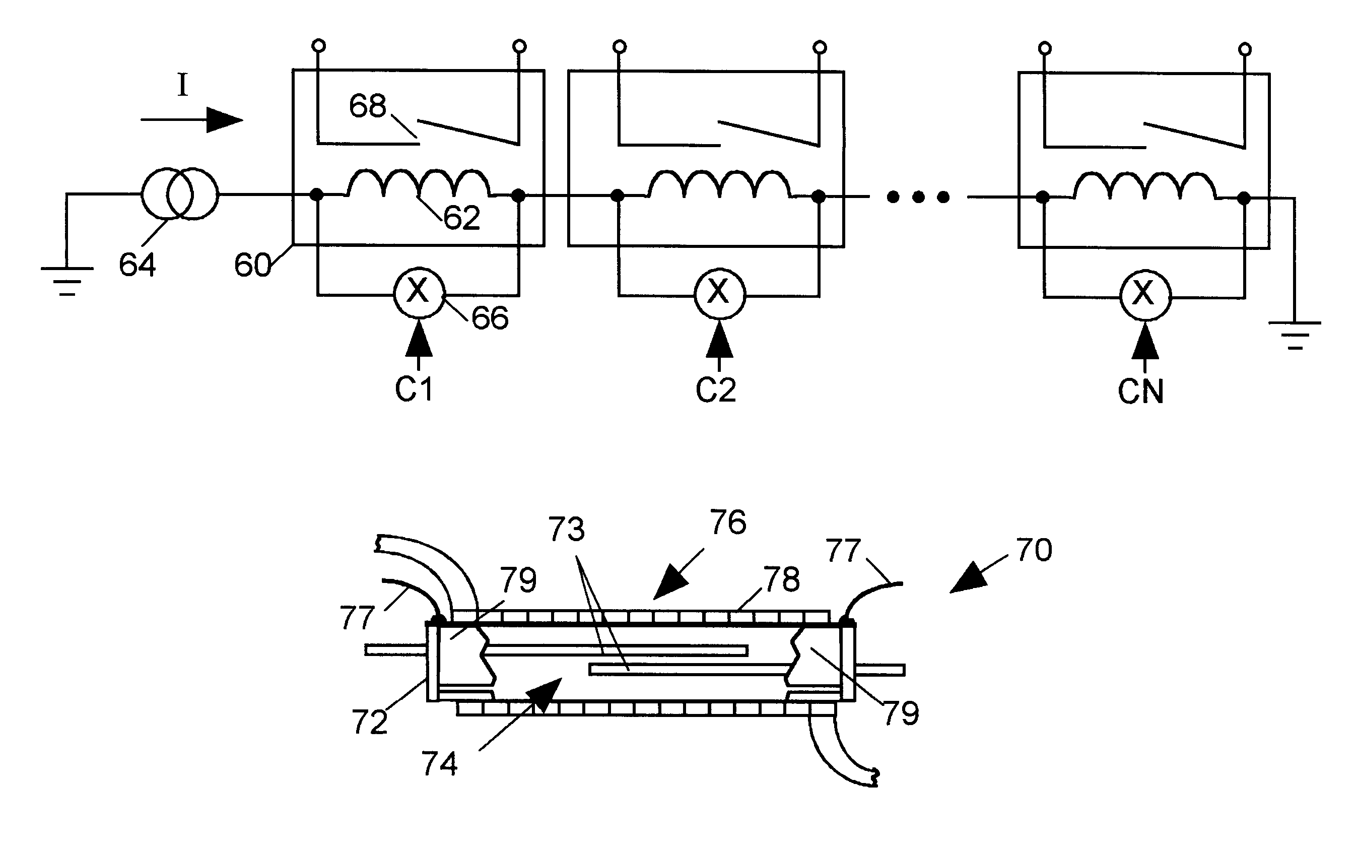
FIG. 9 illustrates a sectional view of a relay 70 in accordance with the invention. Relay 70 includes a glass tube 72, relay contacts 74 within tube 72 formed by reeds 73, and a coil 76 formed by several turns of insulated copper wire 78 surrounding tube 72. Since coil 76 conducts a relatively large current, only a single layer of turns of wire 76 is required. Thus coil 76 adds relatively little thickness to relays 70. In accordance with the invention wire 78 has a rectangular, rather than a circular, cross-section so that there is no wasted space between coil turns. A conductive shield 79 partially surrounding tube 72 acts as a ground surface for the transmission line formed by reeds 73. The spatial arrangement of shield 79 and reeds 73 influences the transmission line impedance. Shield 79 may be formed, for example, by a sheet of conductive foil wrapped partially around tube 72 or by depositing a layer of metal directly on the outer surface of tube 72. Shield 79 may be grounded th...

second embodiment

FIG. 10 is a sectional plan view and FIGS. 11A and 11B are alternative sectional elevation views of a relay 80 in accordance with the invention. Relay 80 has a coil assembly 86 formed by a "flex circuit" comprising conductors 88 embedded in a sheet of flexible insulating material 83,85. The flex circuit coil assembly 86 is wrapped around a glass tube 82 containing reeds 84.

FIGS. 12 and 13 are plan and sectional elevation views of flex circuit forming coil assembly 86 before it is wrapped around tube 82. Referring to FIGS. 10-13, coil assembly 86 is implemented by a flex circuit including flexible, insulating plastic substrate layers 83 and 85 and a set of flexible conductors embedded between insulating material layers 83 and 85. The two flexible layers 83 and 85 of assembly 86 are offset so that conductors 88 are exposed on both ends 92 or 94 of coil assembly 86. When the assembly 86 is wrapped around tube 82, ends 92 and 94 overlap so that ends of adjacent conductors 88 contact wit...

third embodiment

FIGS. 14 and 15 are exploded perspective and sectional elevation views, respectively, of a relay 100 in accordance with the invention. Relay 100 includes a glass tube 116 containing reeds 117 and a coil assembly formed by traces 102 and vias 104 formed on and in a printed circuit board 106. Circuit board 106 includes a lower substrate layer 108 and an upper substrate layer 110 having adjacent recesses 112 and 114 for receiving relay tube 116. conductive layer 119 embedded in lower substrate layer 108 provides a ground surface for the transmission line formed by reeds 117. Alternatively a shield partially surrounding tube 116 (similar to shield 79 of FIG. 9) may provide the ground surface for the transmission line. Tube 117 may have a round cross-section as illustrated in FIG. 15 or may optionally have a rectangular or other cross-section.


PUM


Abstract

A relay includes contacts residing within a glass tube. A coil surrounding the tube and a switch are connected in parallel between two terminals of the relay. A current source supplies a current to the coil and switch. When the switch is open, substantially all of the current passes through the coil and the coil produces a sufficient amount of magnetic flux to close the relay's contacts. When the switch closes, it shunts a sufficient amount of the current away from the coil to reduce the magnetic flux it produces below the level needed to keep the contacts closed. The current source is sized so that the coil requires relatively few turns, thereby allowing the relay to be relatively thin. The coil is formed by a conductor embedded in an insulating substrate surrounding the tube.

Description

1. Field of the InventionThe present invention relates in general to relays and in particular to a current-driven relay having a low profile for use in routing signals on closely spaced circuits or circuit boards of an integrated circuit tester.2. Description of Related ArtFIG. 1 is a block diagram of a portion of a typical prior art integrated circuit (IC) tester 10 including a set of channels 12, one for each of several terminals of an IC device under test (DUT) 14. Each channel 12 includes a channel control and data acquisition circuit 16, a comparator 18 and a tristate driver 20. A relay 24 links an input of comparator 18 and an output of driver 20 to a DUT terminal 26. Another relay 25 connects a parametric measurement unit (PMU) 28 within channel 12 to DUT terminal 26. A host computer 30 communicates with the channel circuits 16 of each channel 12 via a parallel bus 32.Tester 10 can carry out both digital logic and parametric tests on DUT 14. Before starting a digital logic te...

Claims


Application Information

Patent Timeline
IPC IPC(8): H01H51/00H01H51/28G01R31/28G01R31/30G01R31/3193G01R31/319H01H50/10H01H50/00H01H50/44H01H49/00H01H36/00H01H47/04H01H50/04
CPCH01H51/28G01R31/3004G01R31/31926G01R31/3193H01H49/00H01H50/10H01H50/44H01H51/281H01H47/00
Inventor WOHLFARTH, PAUL DANAHALE, ROBERT R.ELLIS, TRAVIS SCOTT
Owner CREDENCE SYSTEMS
Why Eureka
Try Eureka