Dispersion compensation apparatus

Inactive Publication Date: 2001-12-18
NEC CORP
View PDF6 Cites 19 Cited by
  • Summary
  • Abstract
  • Description
  • Claims
  • Application Information

AI Technical Summary

Benefits of technology

Accordingly, an object of the present invention is to provide a dispersion compensation apparatus capable of performing dispersion compensation while the state of polarization between the input and output is maintained.
Another object

Problems solved by technology

However, the polarization of the signal light output from the optical circulator 50 is dependent upon the polarization of the input signal light and there is no assurance that all of the p

Method used


Image

  • Dispersion compensation apparatus
  • Dispersion compensation apparatus
  • Dispersion compensation apparatus

Examples


first embodiment

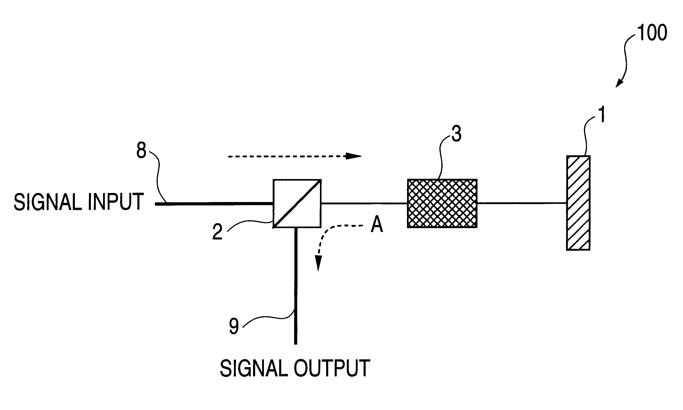
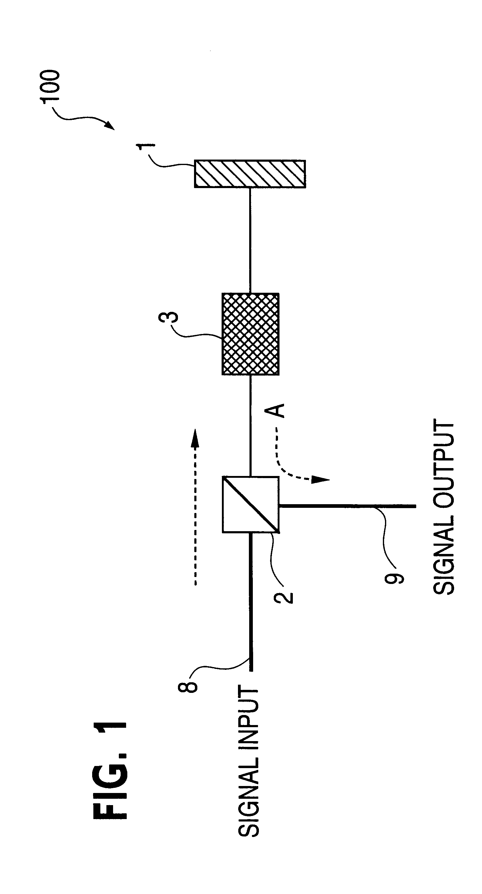
FIG. 1 is a block diagram illustrating a dispersion compensation apparatus according to the invention.

As shown in FIG. 1, a polarization-maintaining dispersion compensation apparatus 100 includes a Faraday rotator mirror 1, a polarization beam splitter 2 and a wavelength dispersion-compensating device 3. The polarization beam splitter 2 has input and output ports 8, 9, respectively, which are first and second polarization-maintaining optical fibers matched to the intrinsic polarization axes (transmission polarization axis and reflection polarization axis) of the polarization beam splitter. The polarization beam splitter acts as a polarization beam multiplexer.

The input signal light in alignment with the transmission polarization axis of the polarization beam splitter 2 passes through the polarization beam splitter 2 and the wavelength dispersion-compensating device (i.e., wavelength dispersion adding device) 3 and is reflected by the Faraday rotator mirror 1 so as to pass through th...


PUM


Abstract

A dispersion compensation apparatus capable of compensating for dispersion while the state of polarization is maintained overall all channels between the input and output ends. Input signal light in alignment with the transmission polarization axis of a polarization beam splitter passes through the multiplexer and a wavelength dispersion-compensating device and is reflected by a Faraday rotator mirror so as to pass through the wavelength dispersion-compensating device again. Owing to the action of the Faraday rotator mirror, the signal light that returns to the wavelength dispersion-compensating device has a polarization that is orthogonal to the polarization that prevailed when the signal light first passed through the device. Thus the polarization beam splitter now operates in the reflective polarization mode with respect to the returning signal light. As a result, 100% of the signal light is output to a Polarization-maintaining optical fiber. Moreover, the polarization is fixed linear polarization.

Description

This invention relates to a dispersion compensation apparatus and optical transmission apparatus in a fiber optic transmission system which uses wavelength division multiplexing.Long-distance, high-capacity wavelength division multiplexed transmission systems has become possible owing to improvements of erbium-doped fiber optic amplifiers and transmission fiber. Further, the rapid spread of the Internet has led to increased demand for larger communication capacity in long-distance fiber optic transmission lines, and an increase in such capacity is under consideration.Generally, in fiber optic transmission, it is known that a large accumulation of wavelength dispersion has the effect of accelerating waveform degradation due to non-linear effects. For this reason, when a transmission line is constructed, care is taken to avoid the occurrence of a large accumulation of dispersion to the greatest extent possible. However, in case of wavelength division multiplexed transmission systems, ...

Claims


Application Information

Patent Timeline
IPC IPC(8): H04B10/18G02B6/00G02B6/024H04B10/2507H04B10/2525H04B10/2543H04B10/294
CPCH04B10/25133H04B10/2525
Inventor ITO, TOSHIHARU
Owner NEC CORP
Why Eureka
Try Eureka