
Cooling apparatus

a technology of cooling apparatus and cooling fluid, which is applied in the direction of domestic cooling apparatus, lighting and heating apparatus, and cooling fluid circulation, etc., can solve the problems of the internal temperature of the object to fall, and achieve the effect of reducing the required installation area, reducing production costs and power consumption

Inactive Publication Date: 2001-12-25
K E
View PDF11 Cites 41 Cited by
  • Summary
  • Abstract
  • Description
  • Claims
  • Application Information

AI Technical Summary

Benefits of technology

According to the present invention, the following advantages are achieved. During a specific period of time such as at nighttime, the means for switching selects the second means for brine circulation as the operating means for circulating brine. Then, the brine that has been cooled by the means for brine cooling is supplied to the ice heat storage tank where the water inside the ice heat storage tank is stored as chilled water.
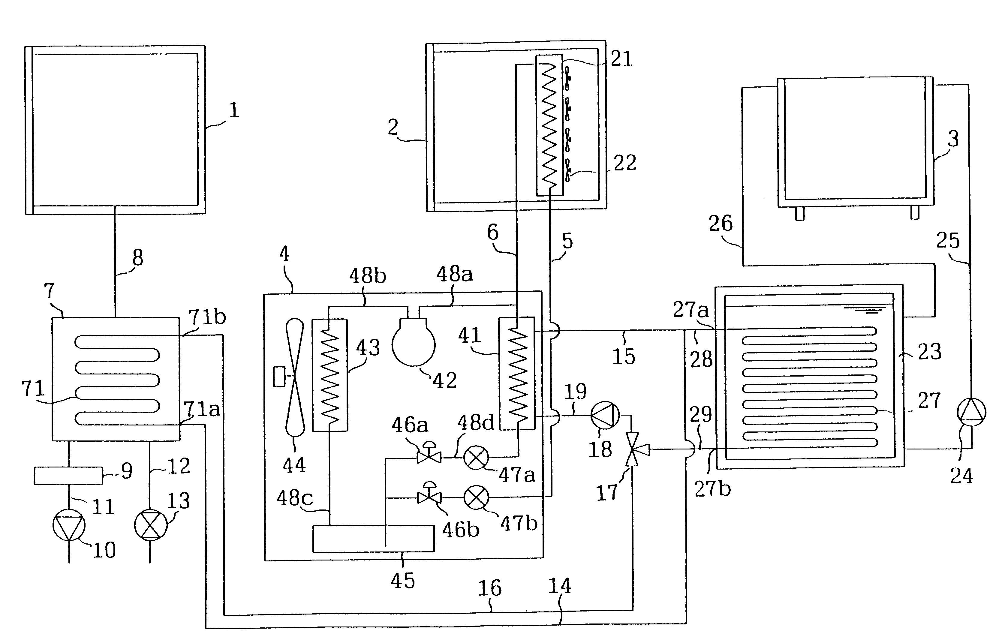
As described above, the means for switching performs a switching operation so that the brine cooled by the means for brine cooling is made to circulate through the ice heat storage tank during the night and is made to circulate through the means for condensation during the daytime. In other words, the cooling of the chilled water cooler during the daytime is achieved by using the chilled water that has been stored in the ice heat storage tank during the night. At the same time, by circulating the refrigerant that circulates in the direct cooler to cool the brine through the means for brine cooling, cooling is also achieved by the direct cooler. Consequently, three coolers can be operated by one means for brine cooling. This achieves a reduction in the required installation area for the entire system and, at the same time, achieves reduction in the production cost and in the power consumption.

Problems solved by technology

This causes the internal temperature of the objects to fall.

Method used


Image

  • Cooling apparatus
  • Cooling apparatus

Examples


Embodiment Construction

The following is an explanation of an embodiment of the present invention given in reference to the attached drawing.

[1. Structure]

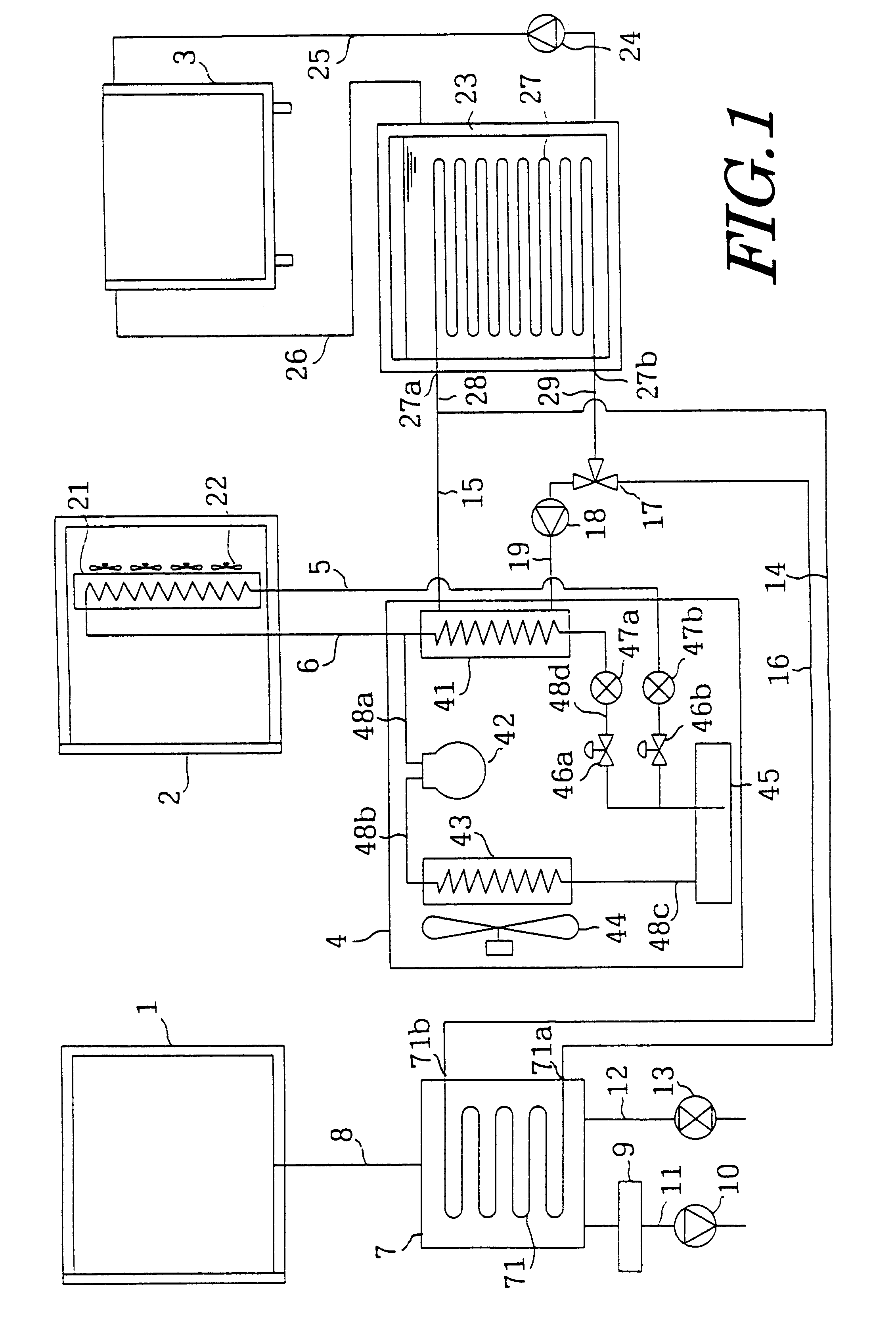
FIG. 1 is a system diagram illustrating the structure of the cooling system in an embodiment of the present invention. In the figure, reference number 1 indicates a vacuum cooler, reference number 2 indicates a blast chiller and reference number 3 indicates a tumble chiller. In this structure, the blast chiller 2 is equivalent to a direct cooler and the tumble chiller 3 is equivalent to the chilled water cooler. It is to be noted that in this embodiment, the vacuum cooler 1, the blast chiller 2 and the tumble chiller 3 each refer to the entire cooling room provided with the corresponding cooler.

Each cooler has a storage space for fruit and vegetables and other foods therein. In more specific terms, a vacuum state is achieved inside the vacuum cooler 1, where foods with high water content such as cooked noodles and side-dishes are stored. In addition, ins...


PUM


Abstract

By supplying a refrigerant utilized for cooling brine at a brine chiller unit (4) to a cooler (21) of a blast chiller (2), the internal space at the blast chiller (2) is cooled. In addition, the brine cooled at the brine chiller unit (4) is supplied to an ice heat storage tank (23) during the night and is supplied to a cold trap (7) during the daytime by switching a three way reversing valve (17). Thus, ice-making and chilled water storage are achieved at the ice heat storage tank (23) during the nighttime so that a tumble chiller (3) performs cooling during the daytime by using the chilled water that has been stored at the ice heat storage tank (23). Consequently, during the daytime, three coolers, i.e., the vacuum cooler (1), the blast chiller (2) and the tumble chiller (3), can be operated with a single brine chiller unit (4).

Description

FIELD OF THE INVENTIONThe present invention relates to a cooling system for cooling materials such as foods, and, in particular, to a cooling system comprising a plurality of different types of coolers.BACKGROUND ARTSanitary management methods adopting the HACCP (Hazard Analysis Critical Control Point) system are beginning to be employed to ensure food safety in various kinds of food industry in recent years. Management items in the HACCP include packaging materials management, ingredient management, cooking and chilling, storage and environment management. In the cooking and chilling aspect of the management system, it has become essential to adopt the so-called Cook-Chill system. The introduction of the Cook-Chill system into meals at schools, companies, hospitals, prisons and the like, and into hotels, restaurants and the like has been deliberated upon and accepted.In the Cook-Chill system, which is a system for cooking and low temperature storage, food that has been cooked is qu...

Claims


Application Information

Patent Timeline
IPC IPC(8): F25D17/00F25D17/02F25D16/00F25B5/02F25B5/00F25D7/00F25D13/00
CPCF25B5/02F25D16/00F25D17/02F25D2400/28F25B41/00
Inventor KAJIMOTO, TAKEKIHARUKAWA, TSUNEO
Owner K E
Learn More