Two-pack urethane foam composition

Inactive Publication Date: 2002-01-08
SUNSTAR GIKEN KK +1
View PDF15 Cites 21 Cited by
  • Summary
  • Abstract
  • Description
  • Claims
  • Application Information

AI Technical Summary

Benefits of technology

(i) As shown in FIG. 1, a shut-off plate 3 for an injection port 2 is mounted with, e.g., a hinge 4 on the inner side of a structural member 1 to be injected and filled. With this configuration, a discharging and injecting nozzle of a mixing head (not shown) is inserted through the injection port 2 or brought into contact therewith. As the foaming material is then injected into the inside of the structural member 1 through the injection port 2 in this state, the shut-off plate 3 is caused to be raised upwardly as indicated by the arrow in FIG. 1. On finishing the injection and suspending the applying of the foaming material or injecting from the-discharging nozzle of the mixing head into the injection port 2, the shut-off plate 3 is allowed to drop down and close the injection port 2, thereby preventing the injected foaming material from back flow after foaming and curing.
(ii) As shown in FIGS. 2(A) (a plan view) and 2(B) (a front view), a rubber-formed member 6 is provided with a cut portion 5 (e.g., an X-shaped cross cut, etc.) which can be opened or closed and through which the foaming material can be injected and filled therein. The rubber-formed member 6 is disposed on the structural member 1 such that the cut portion 5 is fixed into the injection port 2. With this configu

Problems solved by technology

On the other hand, problems may arise in that the weight of the vehicle body is increased and the fuel economy becomes poorer if a thick panel is used as each of the pillar, chassis or the like having a closed sectional structure in order to improve the rigidity and the soundproof property of the cabin.
Various problems, however, may result in injecting the two-pack urethane foam composition into the closed sectional structure.
For instance, when the two-pack urethane foam composition is injected in a fluid state, there are occasions that the injected composition leaks outside or expands from the injection port due to a back flow.
The injected composition leaks or expands even from a small gap of the closed sectional structure so that there is the risk that the appearance of the automobile may be impaired (hereinafter referred to as the first problem).
When such a two-pack urethane foam composition of a curable type having a high reactivity at ambient temperature (0.degree. C.-50.degree. C.) is used, it has been found to raise a practically significant problem that, when it is discharged or injected from a conventional two-pack mixing apparatus, there are occasions in which the two-pack urethane foam composition cures in the mixing apparatus during injecting on site, and thus clogs the mixing apparatus during the injecting process (hereinafter referred to as t

Method used


Image

  • Two-pack urethane foam composition
  • Two-pack urethane foam composition
  • Two-pack urethane foam composition

Examples


examples 1 & 2

AND

COMPARATIVE EXAMPLE 1

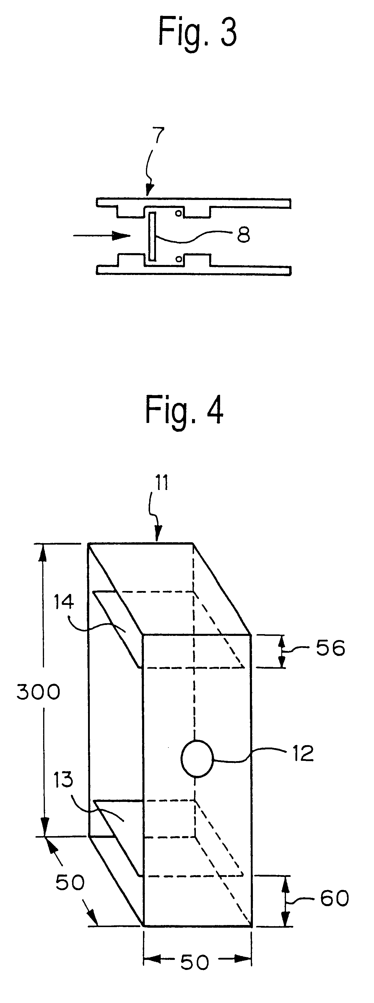
Using the major component (composed of polyol compounds, amine compounds (3,3'-dimethyl-4,4'diaminodicyclohexyl methane), a foaming agent (water) and a reaction catalyst (pentamethylene diethyl tetramine)) and crude MDI as a curing agent in the amounts as indicated in Table 2 below, the resulting mixture was injected into an injection frame 1d (supposed to form a locker portion), as shown in FIG. 11, in accordance with the following procedures by use of the two-pack mixing high-pressure foaming machine VH-3000 installed with the mixing head NR-205 (Toho Kikai Kogyo K.K.). Table 2 below indicates the test results of performance test (packing performance and leakage or expanding), together with the cream time and rise time.

It is to be noted herein that the injection frame 1d comprises component panels (each having a thickness of 15 mm) having dimensions (in mm unit) as shown in FIG. 11, i.e., a rear frame plate 2d, frame plates 3e, 3f, 3g and 3h, a side frame p...

second embodiment

If the relative position would be deviated due to a strain of an individual vehicle body or an error would be caused to occur on the assembly line due to a deviation of the position, however, there would be the possibility that the discharging and injecting nozzle 52 could not be engaged with the injection port if the robot 10 would be controlled so as to be aligned in such an equal manner. In order to avoid an occurrence of such a problem, the present invention in the second embodiment is configured such that a position detecting sensor sensing an amount of deviation between the discharging and injecting nozzle 52 and the injection port of the closed sectional structure of the vehicle body may be provided. The position detecting sensor sends the amount of deviation to the controller 40, and the controller 40 adjusts the position of the hand section, the arm section, and the like, so as to make the amount of deviation zero.

The position detecting sensor may be mounted on the hand sec...


PUM

PropertyMeasurementUnit
Fractionaaaaaaaaaa
Fractionaaaaaaaaaa
Structureaaaaaaaaaa

Abstract

An apparatus is disclosed for injecting an expandable or foaming material in a closed sectional structure of a body. The apparatus is suitable for mass-producing vehicles, such as automobiles efficiently. This apparatus is provided with a manipulator (38) movable to a desired position, a injector (50) fixed to the manipulator, a device (56) for supplying the expandable or foaming material to the injector, and a controller (40) adapted to control the position of the manipulator (10) so that the injector is set in a position in which the foaming material can be supplied to the closed sectional structure of the vehicle body through an injection port of the same closed sectional structure, and also adapted to control the supply device so that the foaming material can be injected and filled in the closed sectional structure thereof by only such an amount that was set in accordance with the volume of the inside of the sectional structure.

Description

The present invention relates to aspects of an invention associated with a two-pack urethane foam composition for reinforcing a closed sectional structure of the body of a vehicle, e.g., automobile, by filling a urethane foam, by injecting the two-pack urethane foam composition, into the closed sectional structure thereof.More particularly, one aspect of the invention relates to a two-pack urethane foam composition which is composed of a two-pack of a polyol compound as a major component and a polyisocyanate compound as a curing agent, and which can form a urethane foam by foaming and curing upon injecting (applying) immediately after mixing the two components at ambient temperature. On the other hand, other aspects of the invention relate to an injection method for injecting the two-pack urethane foam composition, a cured urethane foam-filled vehicle body member having an opening for confirming the injecting and filling of the two-pack urethane foam composition, a cured urethane fo...

Claims


Application Information

Patent Timeline
IPC IPC(8): B29C31/04B29C39/24B29C39/22B29C39/10B29C39/44B29C44/42B29C44/34B29C44/58B29C67/24B60R13/08B01F23/00
CPCB29C31/041B29C39/10B29C39/24B29C39/44B29C44/424B29C67/246B60R13/08B29C44/581Y10T428/24273B29K2075/00B29K2105/04Y10T428/249981Y10T428/249953Y10T428/249976B29C39/02
Inventor YAMASHITA, KIICHIWAKAMORI, TATSUYAMORI, MASAHITOMIYAMOTO, MUTSUHISA
Owner SUNSTAR GIKEN KK
Why Eureka
Try Eureka