Electromechanical wheel brake system

a technology of electronic mechanical and wheel brake, which is applied in the direction of braking systems, mechanical equipment, transportation and packaging, etc., can solve the problems of relatively high construction cost of the known wheel brake device, uncontrolled adjustment of the air play, and relatively inconvenient us

Inactive Publication Date: 2002-01-22
ROBERT BOSCH GMBH
View PDF10 Cites 23 Cited by
  • Summary
  • Abstract
  • Description
  • Claims
  • Application Information

AI Technical Summary

Problems solved by technology

The known wheel brake device is relatively costly in terms of its construction, is friction-encumbered to a considerable degree in its linkage, and requires a frequent switching of the electromagnetic clutch during normal operation.
The restoring of the wheel brake device and the adjusting of the air play takes place in a largely uncontrolled manner.
Only if th

Method used


Image

  • Electromechanical wheel brake system
  • Electromechanical wheel brake system
  • Electromechanical wheel brake system

Examples


Embodiment Construction

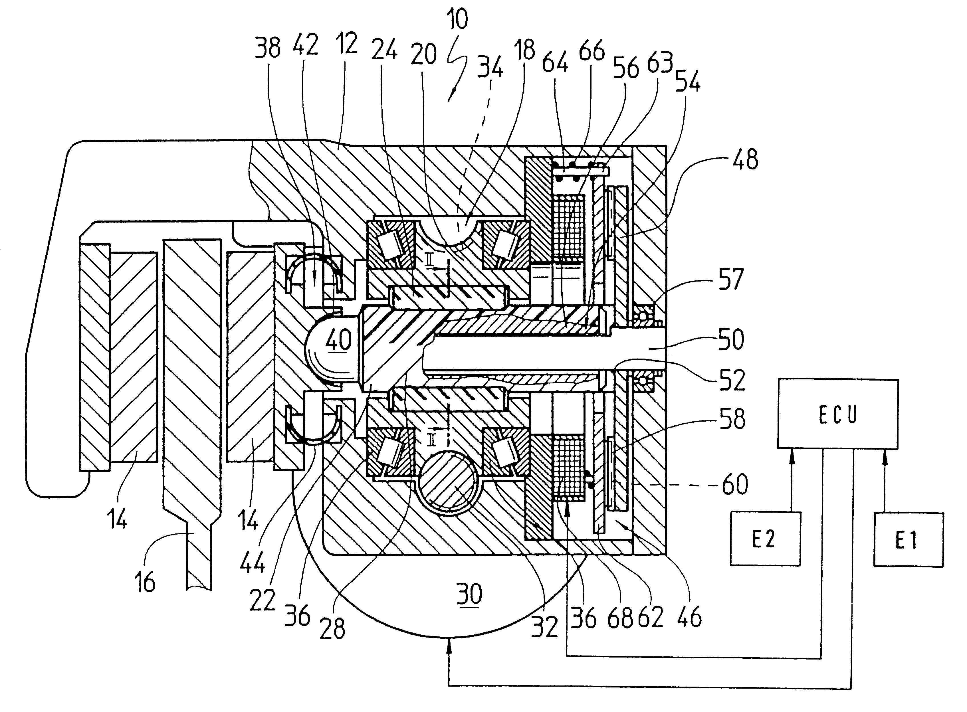
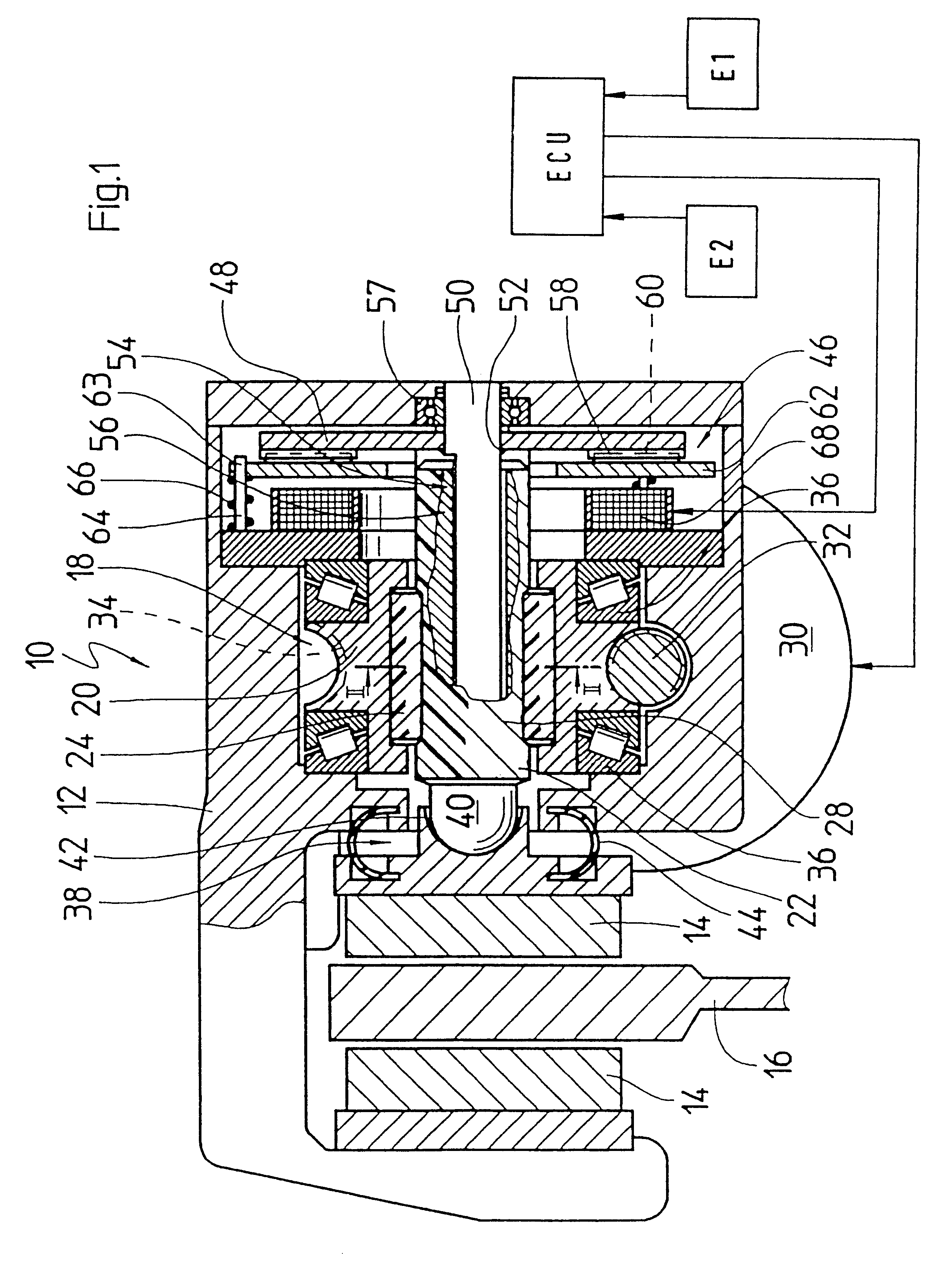
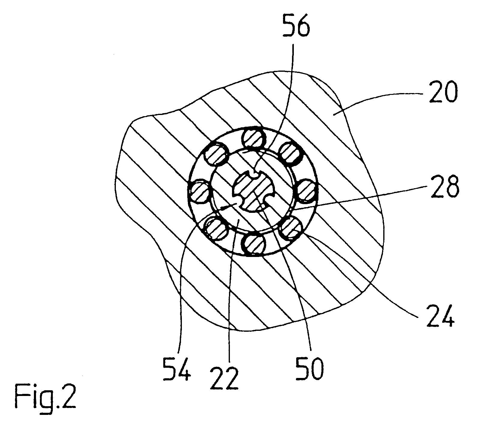
The electromechanical wheel brake device 10 according to the invention as shown in the drawing is embodied as a disc brake. The wheel brake device has a floating caliper 12 in which a pair of wheel brake linings 14 are affixed on both sides of a brake disc 16 that can be set into rotation between the brake linings. In order to press one of the two frictional brake linings 14 against the brake disc 16, the wheel brake device 10 according to the invention has a screw link actuator 18 built into the floating caliper 12. For the sake of very low friction and high efficiency, the screw link actuator 18 is embodied as a roller screw drive in the form of a planetary roller screw drive. The screw link actuator has a threaded spindle 22 disposed coaxially in a spindle nut 20 and eight threaded rollers 24 that are disposed in an intermediary space between the spindle nut 20 and the threaded spindle 22 (see FIG. 2). The threaded rollers 24 engage with a spindle thread 28 of the threaded spindl...


PUM


Abstract

The invention relates to an electromechanical wheel brake device, having a screw link actuator, which is supported in a floating caliper. The screw link actuator can be driven by an electric motor, and can press a frictional brake lining against one side of a brake disc and can press a second frictional brake lining against another side of the brake disc by means of a reaction force by way of the floating caliper. In order to permit a release of the wheel brake device in the event of a malfunction, brake device embodies the screw link actuator as selflocking-free, supporting a spindle nut and a threaded spindle in rotary fashion, and securing the threaded spindle against rotation by means of a releasable rotation prevention device. The threaded spindle is connected in a rotationally secured and axially mobile fashion by means of a positive engagement. In the event of a malfunction, the rotation prevention device is released and the frictional brake lining, which is pressed with force against the brake disc, presses the threaded spindle away from the brake disc, wherein the threaded spindle is set into rotation and moves away from the brake disc.

Description

PRIOR ARTThe invention relates to an electromechanical wheel brake device for a motor vehicle.An electromechanical wheel brake device that defines a similar system has been disclosed by EP-A-0 275 783. The prior art wheel brake device has an axially immobile threaded spindle which can be connected to a first gear by means of a switchable electromagnetic clutch. A rotatable and axially mobile spindle nut on the threaded spindle supports a second gear, which can be coupled to the spindle nut in a manner that depends on the axial force. The two gears, together with a third gear that can be driven by an electric motor 30 and engages the two other gears, constitute a differential drive. The spindle nut supports a longitudinally mobile piston for pressing a frictional brake lining against a brake body.In a braking maneuver, the electric motor and the electromagnetic clutch are supplied with current. The rotary driven threaded spindle moves the spindle nut, which is not driven at first, in...

Claims


Application Information

Patent Timeline
IPC IPC(8): B60T13/74B60T13/00F16D65/14F16D65/18F16D65/28
CPCB60T13/741F16D65/18F16D2121/24F16D2127/06F16D2125/52F16D2125/587F16D2125/40
Inventor SCHAFFER, WOLFRAM
Owner ROBERT BOSCH GMBH
Why Eureka
Try Eureka