Method for the simultaneous modernization of a plant for ammonia production and a plant for urea production

a technology for ammonia production and urea production, which is applied in the directions of ammonia preparation/separation, liquid-gas reaction process, inorganic chemistry, etc., can solve the problems of rapid overload, unavoidable increase of flow rate, and increase accordingly of section capacity

Inactive Publication Date: 2002-01-22
UREA CASALE SA
View PDF6 Cites 12 Cited by
  • Summary
  • Abstract
  • Description
  • Claims
  • Application Information

AI Technical Summary

Problems solved by technology

One of the main problems that is encountered when a simultaneous increase of production capacity is considered in existing plants for ammonia and urea production, which are correlated to each other, is that of increasing accordingly the capacity of the sections upstream of the respective synthesis reactors.
In particular, the decarbonation, methanation and compression section of the ammonia synthesis gas as well as the compressors of the refrigeration cycles within the synthesis loop of ammonia and the compression section of the flow comprising carbon dioxide fed to the urea synthesis section are bottlenecks for the capacity increases, in that they are rapidly overloaded by the unavoidabl

Method used


Image

  • Method for the simultaneous modernization of a plant for ammonia production and a plant for urea production
  • Method for the simultaneous modernization of a plant for ammonia production and a plant for urea production
  • Method for the simultaneous modernization of a plant for ammonia production and a plant for urea production

Examples


case 1

erational conditions in the synthesis section of urea (synthesis reactor) are as follows

pressure: .ident.140.div.150 abs bar

temperature: 183.div.188.degree. C.

mol. NH.sub.3 / CO.sub.2 : .ident.3

mol. H.sub.2 O / CO.sub.2 : .ident.0.5

.eta.: 60% (yield conversion)

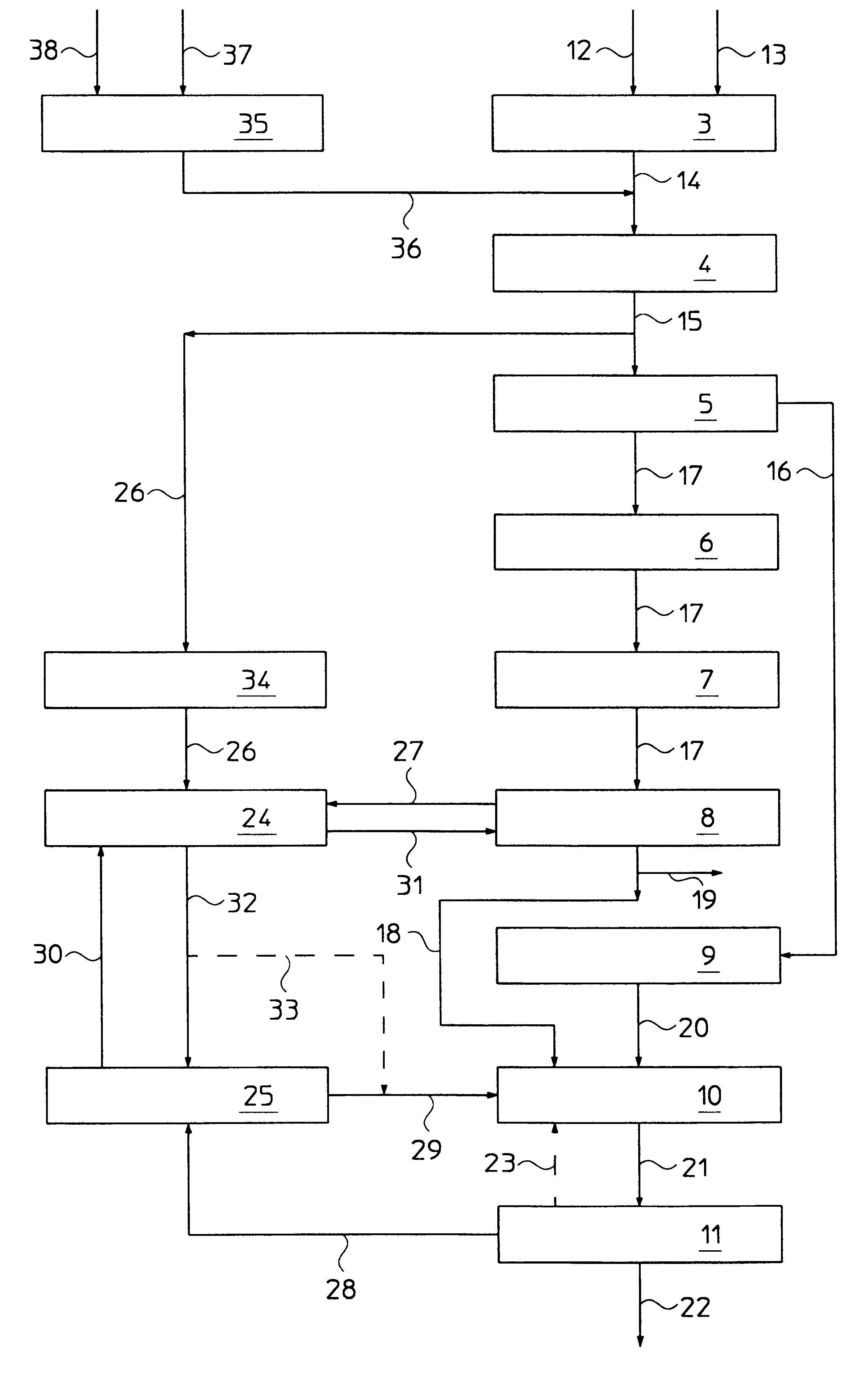
The solution of urea coming out from the synthesis reactor is stripped in a conventional manner in a stripper, using feed CO.sub.2 as stripping agent. The vapours so obtained are partially condensed in a carbamate condenser and supplied to the synthesis reactor together with the recycled aqueous solution of carbamate coming from the urea recovery section.

The simultaneous modernisation of the ammonia plant and of the urea plant just described according to the method of the present invention, allows to achieve a productive capacity of the urea plant of 3500 MTD. Furthermore, the operational conditions in the urea synthesis section were as follows:

pressure: .ident.140.div.150 abs bar

temperature: 185.div.189.degree. C.

mol. NH.sub.3 / ...

case 2

erational conditions in the synthesis section of urea (synthesis reactor) are as follows.

pressure: .ident.140.div.150 abs bar

temperature: 185.div.190.degree. C.

mol. NH.sub.3 / CO.sub.2 : .ident.3.2

mol. H.sub.2 O / CO.sub.2 : .ident.0.5

.eta.: 62% (yield conversion)

The solution of urea coming out from the synthesis reactor is stripped in a conventional way in a stripper, according to self-stripping conditions. The vapours so obtained are condensed in a first condenser and recycled to the reactor. The solution of urea coming out from the stripper is in turn distilled at 18 abs. bar in a medium pressure step and at 4 abs. bar in a low pressure step and is passed on to the vacuum concentration section, so as to obtain 99.7% Wt. fused urea . The vapours rich in ammonia coming out from the medium pressure distillation section are partially condensed in a second condenser in presence of a recycled aqueous solution of carbamate and are passed on to a rectifying column: the head product is pure ...


PUM

PropertyMeasurementUnit
Fractionaaaaaaaaaa
Fractionaaaaaaaaaa
Fractionaaaaaaaaaa

Abstract

A method for the simultaneous modernization of a plant for ammonia synthesis and a plant for urea synthesis, provides-inter alia-the arrangement of a carbamate synthesis section and a carbamate decomposition section, in order to obtain a predetermined amount of carbamate in aqueous solution and of hydrogen and nitrogen in gaseous phase which are fed to the existing sections for urea synthesis, respectively ammonia synthesis. Thanks to this method of modernization it is possible to remarkably increase the production capacity and at the same time to reduce the energy consumption of the urea and ammonia plants without being forced to replace or anyway overload the existing sections of decarbonation, methanation and compression, in general.

Description

FIELD OF APPLICATIONThe present invention relates to a method for the simultaneous modernisation of a plant for ammonia production and of a plant for urea production.More specifically, the invention relates to the simultaneous modernisation of a plant for ammonia production of the type comprising a section for the production of raw ammonia synthesis gas, which comprises carbon monoxide, hydrogen and nitrogen, a carbon monoxide conversion section, a decarbonation section, a methanation section, a compression section of the ammonia synthesis gas and an ammonia synthesis section, provided in series, and a plant for urea production of the type comprising a carbon dioxide compression section, a urea synthesis section and a urea recovery section, provided in series.In the following description and enclosed claims, by the term "modernisation", it is intended to mean the modification of a pre-existing plant with the purpose of improving its performance and obtaining, for example, an increas...

Claims


Application Information

Patent Timeline
IPC IPC(8): C01C1/04C01C1/00C07C273/10C07C273/00C07C275/00
CPCC07C273/10C01C1/0488Y02P20/52
Inventor PAGANI, GIORGIOZARDI, FEDERICO
Owner UREA CASALE SA
Why Eureka
Try Eureka