Clamp for electroplating articles

a technology for electroplating articles and clamps, which is applied in the direction of building scaffolds, candle holders, lighting support devices, etc., can solve the problems of high rate of corrosion, high risk of screw damage to the board, so as to relieve the pressure

Inactive Publication Date: 2002-01-29
M & B PLATING RACKS
View PDF14 Cites 43 Cited by
  • Summary
  • Abstract
  • Description
  • Claims
  • Application Information

AI Technical Summary

Benefits of technology

Preferably, said pressure member is a screw threadingly engaging said clamp main body through a through-bore provided therein, said screw being able to gradually apply pressure on said spring clip second arm when it is rotated in a first direction to pivot said second arm towards said first arm and consequently pivot said first and second arms toward

Problems solved by technology

A first problem with the Wismer device is that the screw is likely to damage the board when it is rotated and pressed against the board.
The damage to these board results mainly from the rotational movement and associated shearing effect of the screw, not from the transverse pressure applied on the board.
In the case of the Wismer device, the resilient end seal provided at the screw tip around the electrically conducting core, is likely to enhance this problem due to the higher friction coefficient between the resilient seal material and the board.
However, this seal is essential, or else the acid solution would have free access to the conducting core, the latter then being cor

Method used


Image

  • Clamp for electroplating articles
  • Clamp for electroplating articles
  • Clamp for electroplating articles

Examples


Embodiment Construction

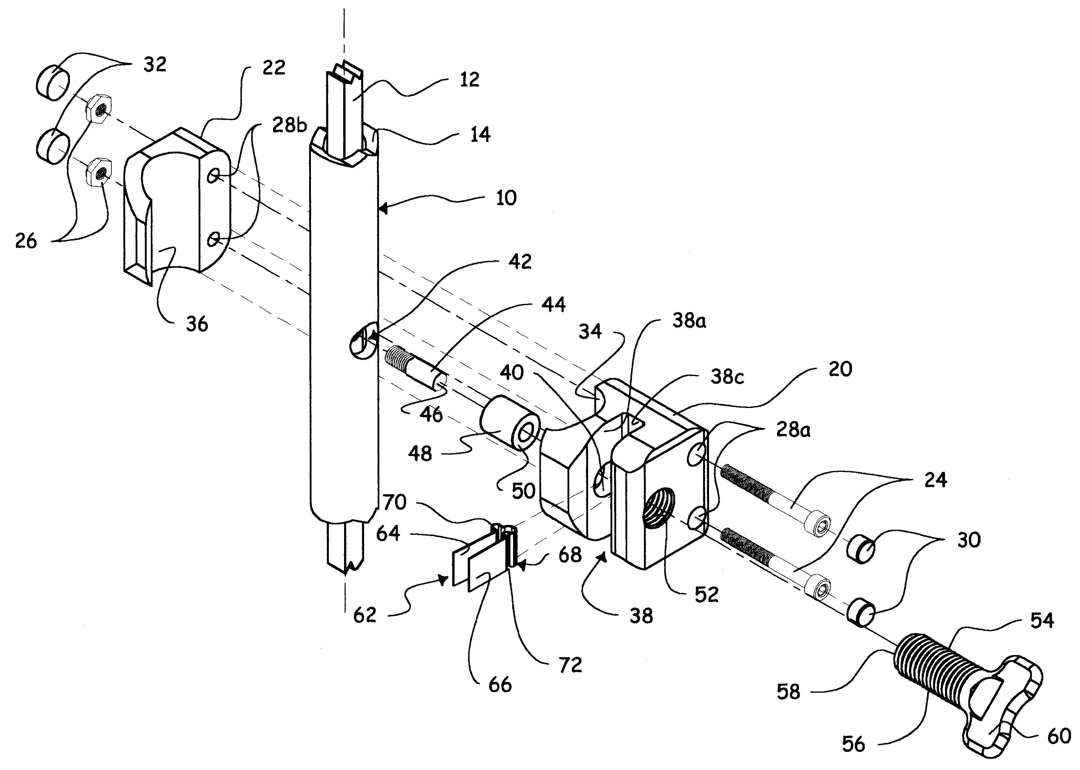
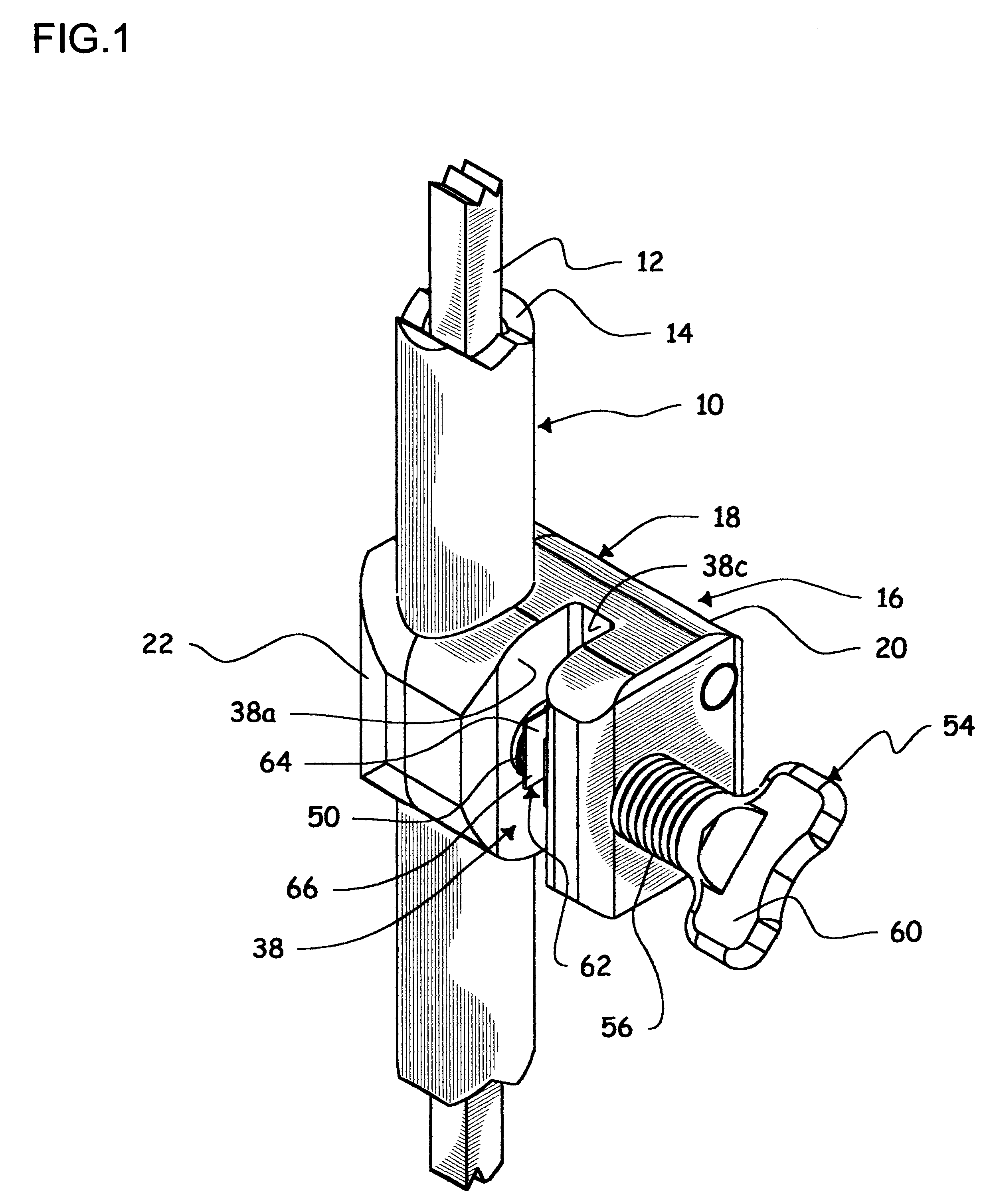
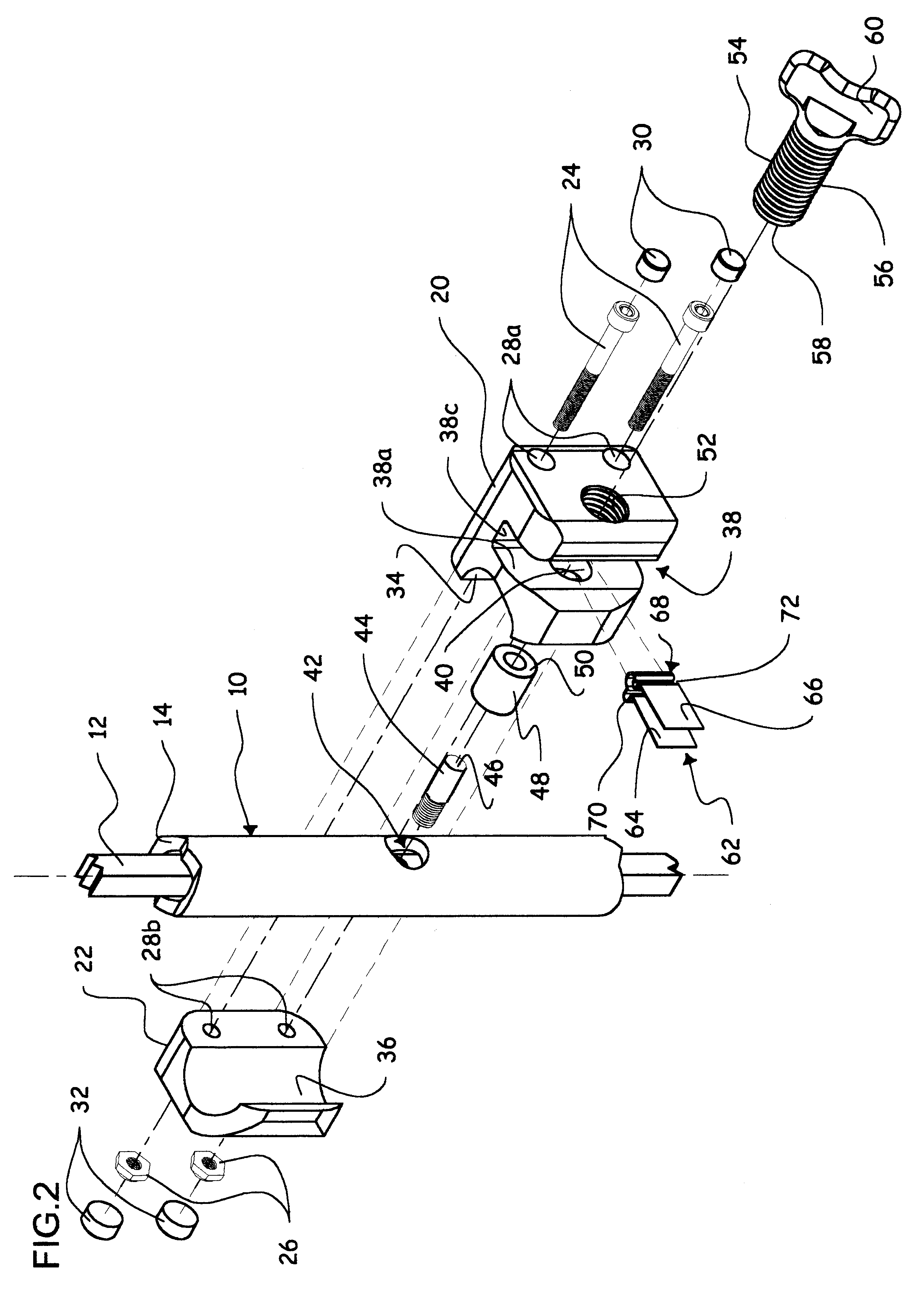
FIGS. 1 to 4 show a portion of an electroplating rack in the form of a vertical bar 10 which is attached to a cathode flight bar (not shown). Bar 10 is formed of an inner electrically conducting core rod 12, e.g. made of copper and having a square cross-section (although any suitable shape is acceptable), which is electrically connected to the cathode flight bar, and of an outer electrically insulating and fluid-tight sheath 14, e.g. made of plastic and having an annular cross-section (although any suitable closed shape is acceptable).

A clamp 16 according to the invention is attached to bar 10 as described hereinafter, for holding an article such as a board to be electroplated, to form an integrated circuit board. Clamp 16 comprises a main body or frame 18 formed of a first and a second block 20, 22 attached to each other by bolts 24 and nuts 26 running through channels 28a, 28b formed coextensively through first and second blocks 20, 22, respectively. Caps 30, 32 sealingly block ch...


PUM

PropertyMeasurementUnit
Pressureaaaaaaaaaa
Currentaaaaaaaaaa
Electrical conductoraaaaaaaaaa

Abstract

An electroplating rack includes a cathode flight bar from which depends an insulated rack bar over an acid bath. A clamp is fixed to the rack bar, and has a bridge electrically connected to the flight bar through a conducting core inside the insulated rack bar. The clamp has a main body made of plastic, which includes a slot in which protrudes the bridge. An electrically conducting spring clip is installed in the slot, and is formed of two arms continuously biased into a spreaded, opened condition in the slot. A screw carried by the main body, when rotated in a first direction, can force the spring clip into a closed condition, in which it can hold an article to be electroplated between its two arms, and in which one of the spring clip arms is forced against the bridge member. Thus, electrical current can pass through the rack flight bar and conducting core, then through the bridge member, the spring clip and finally into the article to be electroplated. Once the rack is lowered to submerge the article into the acid bath, the latter will be electroplated with this current passing through the article.

Description

The present invention relates to article holders or clamps for electroplating articles.It is known in the art of electroplating to use frames on which are removably installed circuit boards or the like articles to be electroplated, for holding them while they are being submerged in large acid tanks or baths. The acid bath is one of several steps involved in the manufacture of a printed circuit board. The acid solution is usually either chloridric acid or sulfuric acid. The overhanging flames are made of an electrically conducting material sealed in a fluid-tight and electrically insulating material to substantially slow down the corrosive effects of the acidous vapors from the bath of acid, and are sealingly electrically connected to the articles to be plated. The frames are connected to a cathode element, or flight bar, and are subjected to an electrical current which is transmitted through the frame structure, the article and the liquid acid. An anode element is also submerged in ...

Claims


Application Information

Patent Timeline
IPC IPC(8): C25D17/06
CPCC25D17/06
Inventor BROWN, HOWARD
Owner M & B PLATING RACKS
Why Eureka
Try Eureka