Electronic components incorporating ceramic-metal composites

a technology of ceramic and metal composites, applied in the field of electronic components, can solve the problem that metal pastes represent a significant cost to the manufacturer of electronic components

Inactive Publication Date: 2002-02-12
COORSTEK INC
View PDF37 Cites 17 Cited by
  • Summary
  • Abstract
  • Description
  • Claims
  • Application Information

AI Technical Summary

Problems solved by technology

One of the drawbacks of screening metals into vias and conductor paths is that the metal pastes represent a significant cost to the manufacturer of the electronic com

Method used


Image

  • Electronic components incorporating ceramic-metal composites
  • Electronic components incorporating ceramic-metal composites
  • Electronic components incorporating ceramic-metal composites

Examples


Embodiment Construction

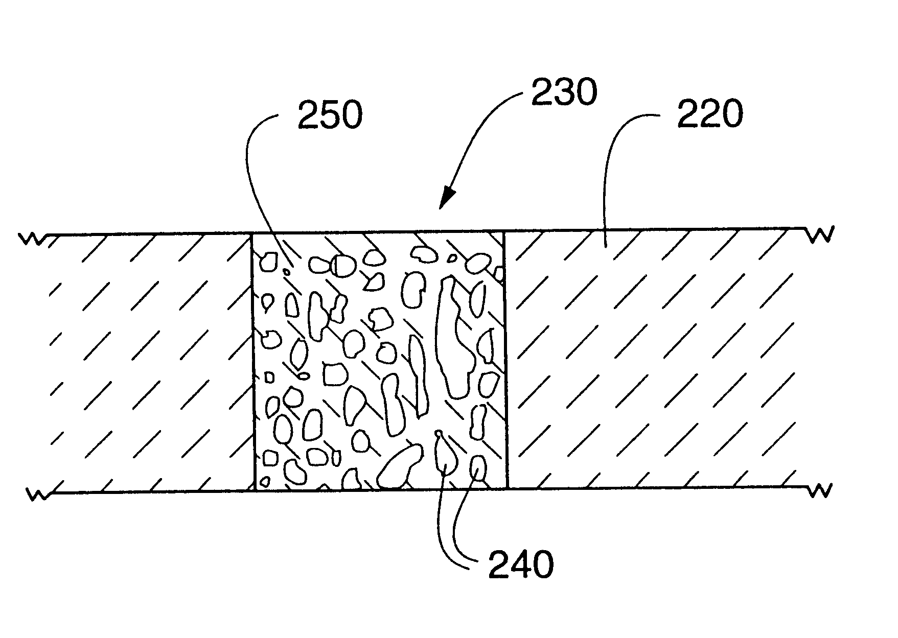
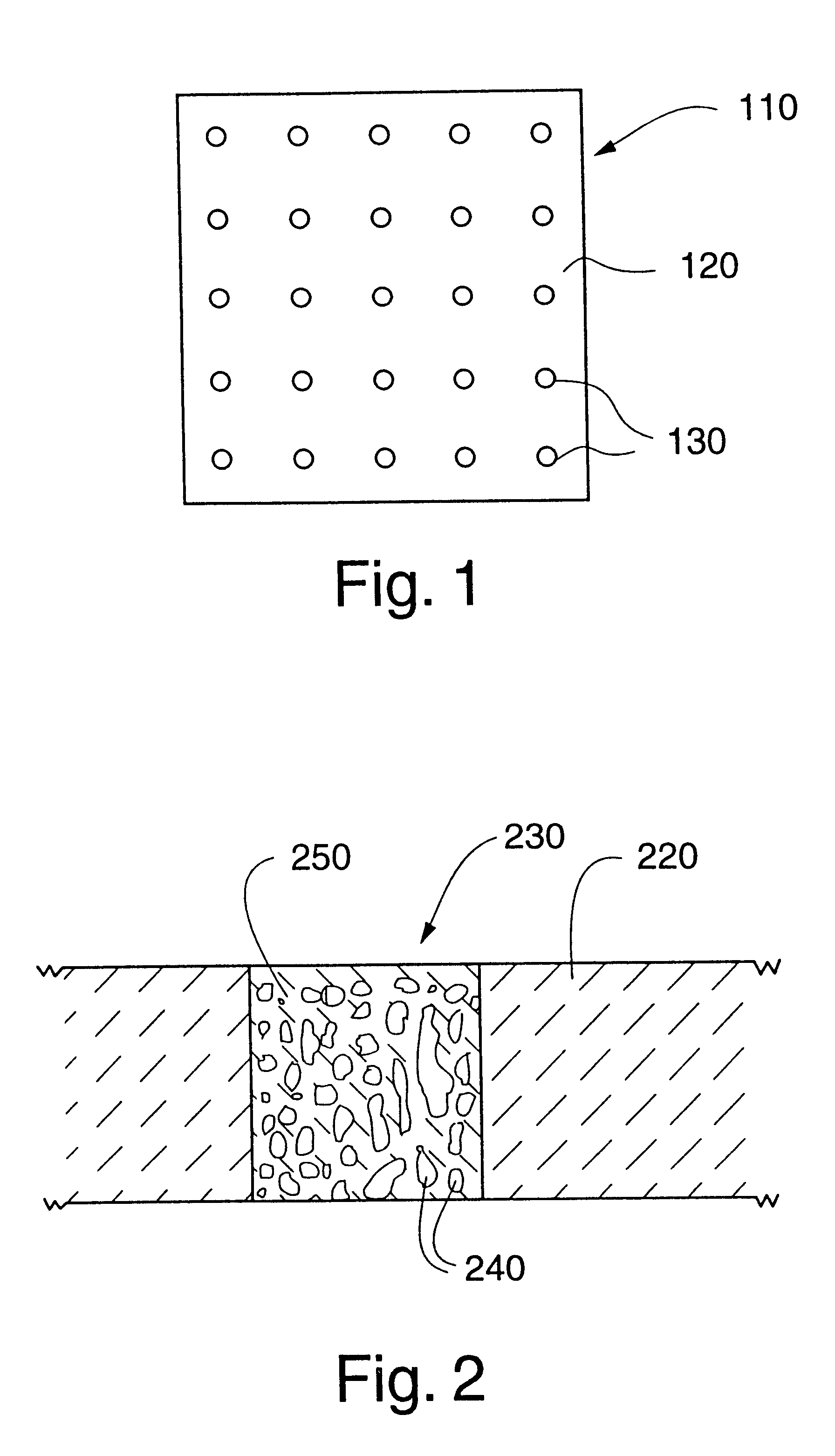
The present invention is directed to a method for making a ceramic substrate, or sheet, that includes ceramic-metal composite portions that are useful for conducting electricity or heat. Such ceramic substrates can advantageously be formed into MLC devices that include multiple layers of ceramic sheets having ceramic-metal composite vias and ceramic-metal composite conductor paths connecting the vias. The ceramic sheets are preferably stacked, laminated and sintered before the metal is infiltrated into the MLC device to form the composite portions.

In a broad aspect, the present invention relates to fabricating ceramic sheets having selected portions of ceramic having open porosity and contacting the ceramic with a molten metal to infiltrate the metal into the open porosity. The infiltration is preferably accomplished in the absence of significant overpressures and preferably does not require a reducing atmosphere.

According to one aspect of the present invention, ceramic sheets are f...


PUM

PropertyMeasurementUnit
Angleaaaaaaaaaa
Temperatureaaaaaaaaaa
Electrical conductoraaaaaaaaaa

Abstract

The present invention relates to electronic components and in particular relates to ceramic-based electronic components wherein a portion of the component comprises a metal-infiltrated ceramic. In a preferred embodiment, the metal-infiltrated ceramic comprises copper metal.

Description

1. Field of the InventionThe present invention relates to electronic components fabricated using ceramic substrates, such as multi-layer ceramic devices. More particularly, the present invention relates to electronic components having ceramic layers that incorporate ceramic-metal composite materials and methods of producing such components.2. Description of Related ArtMulti-layer ceramic (MLC) devices are fabricated from a plurality of stacked ceramic sheets (substrates), wherein each sheet has a particular screened metal pattern on its planar surface and a selected pattern of feed-through vias, or holes, formed through the sheet. The vias in the ceramic sheets are usually filled in the unfired or "green" state with a slurry of refractory metal paste, i.e., tungsten particles suspended in an organic vehicle. Screen printing techniques, through either a stencil or a screen, are typically used to apply the planar metallization and to force the metallizing paste into the vias. Selected...

Claims


Application Information

Patent Timeline
IPC IPC(8): B01D53/04B01D63/06B01D29/11C04B41/51C04B37/02C04B41/89C04B41/88C04B41/52C04B41/45C04B37/00C22C29/12C22C1/10C22C29/00F02F3/00H01L21/02H01L23/498H01L23/52H01L21/48H01L23/538H01L23/48H05K3/40F02B3/00F02B3/06H05K1/03F01L3/02F01L3/22F02F7/00
CPCB01D29/111B01D53/02B01D63/061B01D63/066B32B18/00C04B41/009C04B41/5127C04B41/5144C04B41/52C04B41/88C04B41/89C22C1/1015C22C1/1036C22C29/12F01L3/02F01L3/22F02F3/00F02F7/0087H01L21/486H01L23/49827H01L23/5384H05K3/4061C04B41/4523C04B41/4572C04B41/4582C04B41/5093C04B41/5133C04B35/10C04B38/0003B01D29/31B01D53/0438B01D2201/0446B01D2253/104B01D2253/112B01D2253/25B01D2253/30B01D2253/311B01D2259/4145C04B2111/00793C04B2237/343C04B2237/68C22C2001/1063F01L2101/02F02B3/06F05C2201/0415F05C2203/0895F05C2253/16H01L2924/09701H05K1/0306H05K2201/0116H05K2203/128H01L2924/0002Y10S148/069C04B2237/064C04B2237/341C04B2237/366C04B2237/592C04B2237/62Y10T156/1056Y10T428/24926H01L2924/00Y10T428/249957Y10T428/24997F01L2301/02C22C1/1063
Inventor RITLAND, MARCUS A.READEY, DENNIS W.SIBOLD, JACK D.STEPHAN, JAMES E.
Owner COORSTEK INC
Why Eureka
Try Eureka