Device for detecting the position of two bodies

a technology for detecting the position of two bodies and devices, applied in the direction of walking sticks, navigation instruments, instruments, etc., can solve the problems of not being able to detect all six possible motion components, restricted known devices, and moreover extraordinary structural complexity, etc., to achieve high resolution measurement, easy to carry out measurements, and high accuracy

Inactive Publication Date: 2002-02-26
DR JOHANNES HEIDENHAIN GMBH
View PDF3 Cites 15 Cited by
  • Summary
  • Abstract
  • Description
  • Claims
  • Application Information

AI Technical Summary

Benefits of technology

The object of the present invention is to provide a device which, using a simple design, allows to detect all six motion components.
According to the present invention, an exact spatial alignment of the components is not required, and the parallelism of the measuring system components relative to two planes does not have to be guaranteed to carry out the measurement. In the present invention, two bodies are to be arranged roughly parallel to each other relative to only one plane, which is additionally facilitated by the distance-measuring devices resulting in three identical distances that equal to both planes being parallel. A jointing operation, as was required in previous cases, is not required, thus making it considerably easier for measurements to be carried out.
Using incremental position-measuring systems having grating divisions for position and situation measuring results in a high accuracy, high resolution measurement, low susceptibility to failure (electromagnetic), stability with regard to atmospheric influences such as air temperature, humidity, and pressure that can have a disruptive effect when using laser interferometers.

Problems solved by technology

In known position measuring devices, it is generally not possible to detect all six possible motion components.
The known devices are not only restricted with regard to the detection of motion components, but moreover have an extraordinary degree of structural complexity.
Compared to this, the use of cuboidal measuring standards having two or more reference surfaces requires a considerably greater technical effort in carrying out measurements.

Method used


Image

  • Device for detecting the position of two bodies
  • Device for detecting the position of two bodies
  • Device for detecting the position of two bodies

Examples


Embodiment Construction

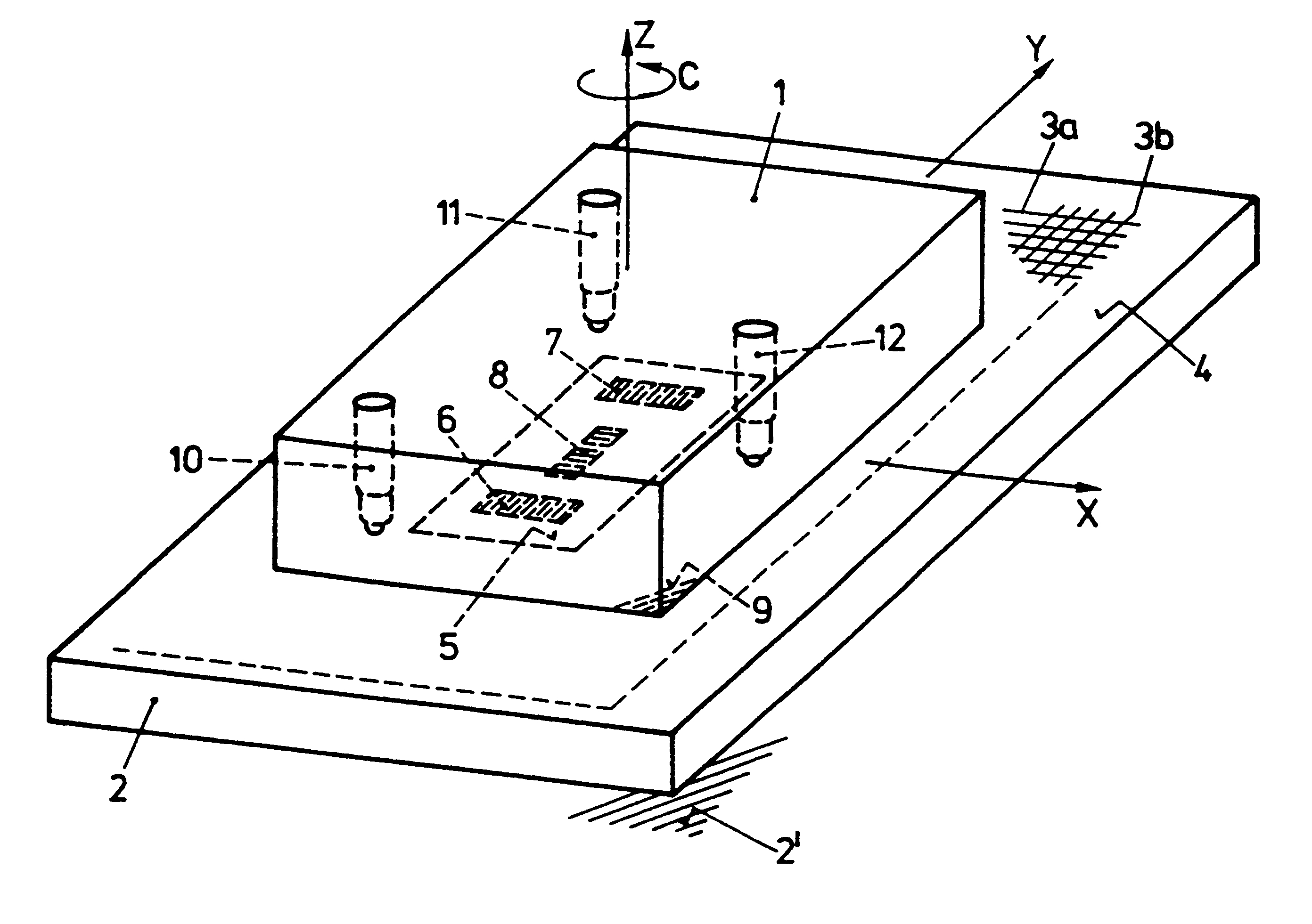
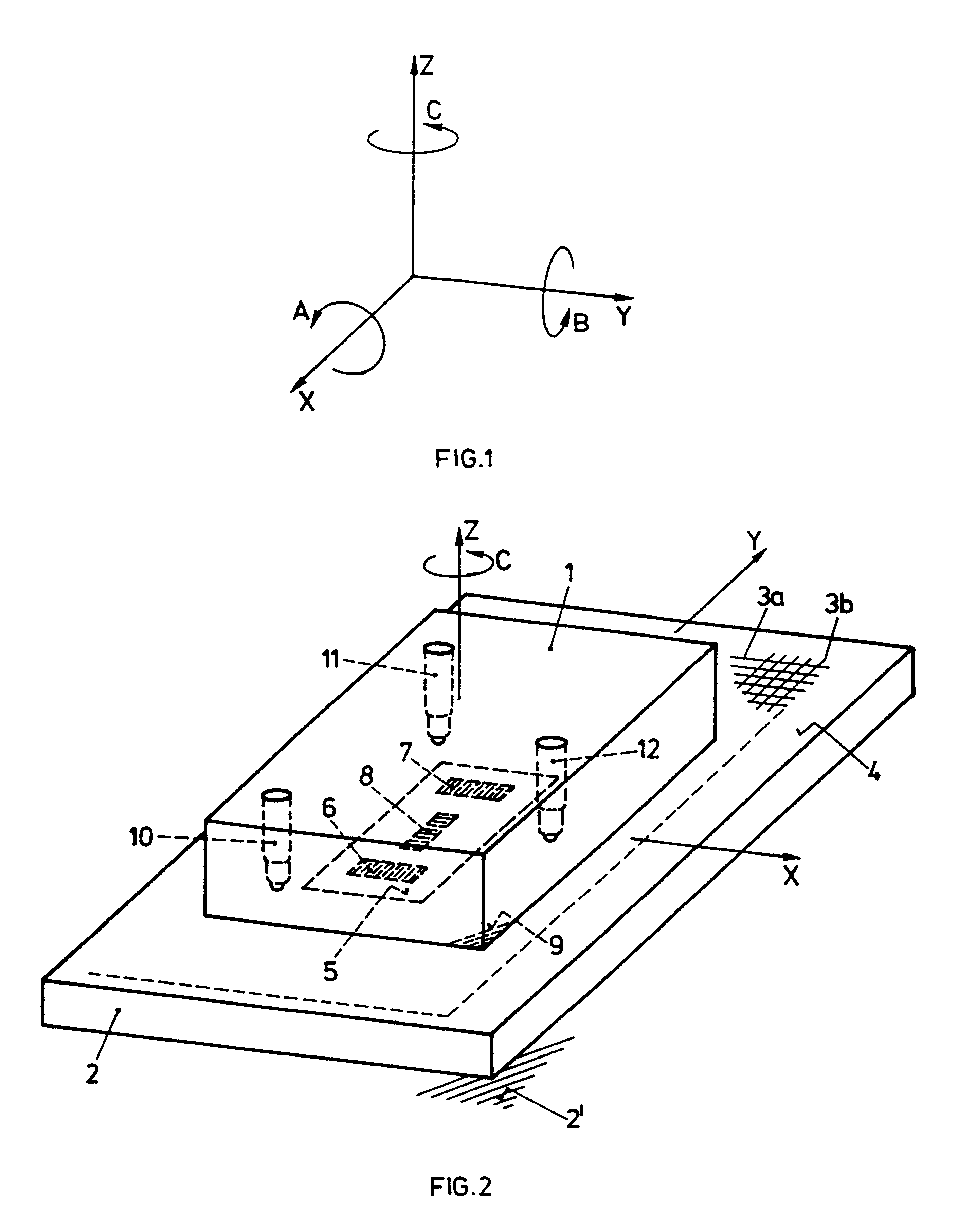
A typical rigid body has six degrees of freedom: three translational motion components in the X, Y and Z axes, and three rotational degrees of freedom A, B and C. The position and orientation of a body are completely described by specifying the six degrees of freedom. By specifying the time characteristic of these six quantities, the motion of the body is defined completely. The arrangement of these degrees of freedom is shown in FIG. 1 on the basis of a coordinate system standardized according to ISO.

The detection of the relative position of a tool and a workpiece on machine tools or other automatic handling systems constitutes a central object of the metrology of a machine. A series of measuring instruments have been developed for this purpose. It is a characteristic of conventional devices that only sub-components of the relative motions can be detected. Generally it is not possible to detect all six degrees of freedom which describe the relative motion completely.

Consequently, t...


PUM


Abstract

A device for detecting six components of the relative motion of two bodies during a primarily two-dimensional translatory basic motion is described. The device has a plate which is provided with a two-dimensional, optical grating, and which is equipped with a plurality of vertically arranged devices for distance measuring. A second element which is composed of an arrangement of two or three optical gratings, and a plane surface which is parallel to the gratings is included. The optical gratings permit a detection of the relative displacements in X- and Y- directions parallel to the lower plate via an evaluation of the variations in intensity of the reflected light.

Description

BACKGROUND INFORMATIONThe present invention relates to a device for detecting and / or adjusting the position of two bodies capable of being moved relative to each other, the bodies having cross gratings. The invention is thus a measuring device allowing the detection of the six possible motion components taking place during a primarily plane, two-dimensional translatory relative motion of two bodies.SUMMARY OF RELATED ARTIn known position measuring devices, it is generally not possible to detect all six possible motion components. In addition, reference bodies used as measurement standards, having two or three plane reference surfaces precisely arranged relative to each other, are required to perform the measurement.The known devices are not only restricted with regard to the detection of motion components, but moreover have an extraordinary degree of structural complexity. Generally, they are based on the use of a linear measurement standard.The object of the present invention is to...

Claims


Application Information

Patent Timeline
Patent Type & Authority Patents(United States)
IPC IPC(8): G01B11/00G01B7/004G01B11/27
CPCB82Y15/00G01B11/002G01B7/004
Inventor BRAASCH, JANCALLIMICI, CHRISTIANWEIKERT, SASCHA
Owner DR JOHANNES HEIDENHAIN GMBH
Why Eureka
Try Eureka