Variable reflectivity mirror for increasing available output power of a laser

a reflectivity mirror and laser technology, applied in the field of lasers, can solve the problems of fixed reflectivity, reduced optical output, and complicated selection of reflectivity that optimizes outpu

Inactive Publication Date: 2002-02-26
TERRACOMM RES
View PDF14 Cites 14 Cited by
  • Summary
  • Abstract
  • Description
  • Claims
  • Application Information

AI Technical Summary

Benefits of technology

According to the invention, output for a laser is greatly increased by altering the transmitivity of a superconductor layer which serves as one of the mirrors of the laser cavity. The superconductor layer is switched between a superconductive state, having a high reflectivity, and a non-superconductive state, having a lower reflectivity. When the mirror is in its superconducting state, power in the laser cavity will reach a high level and light output will be low, and when the mirror is in its non-superconducting state, power output will be high and the cavity power will be lowered.

Problems solved by technology

Unfortunately, these mirrors have a fixed reflectivity.
However, selecting a reflectivity that optimizes output is more complicated.
Although this maximizes optical feedback, amplification, and energy build up in the cavity, it also reduces optical output to zero.
The result is low optical output and the laser does not lase.
This method suffers from the slow speed of mechanical devices.
Disadvantages of this method include: it requires a high speed, high voltage electrical pulse source; these intense electrical pulses can produce severe electrical interference in nearby equipment; and the optical crystal and polarizers are optically lossy even in the high Q state and are subject to optical damage.
However, this method is limited to kHz repetition rates.
Note that Q switching is not practical for most visible gas lasers or organic dye lasers as the population lifetimes are a few nanoseconds.
The time over which a population can be built up and stored is just too short for a pulse to develop.

Method used


Image

  • Variable reflectivity mirror for increasing available output power of a laser
  • Variable reflectivity mirror for increasing available output power of a laser
  • Variable reflectivity mirror for increasing available output power of a laser

Examples


Embodiment Construction

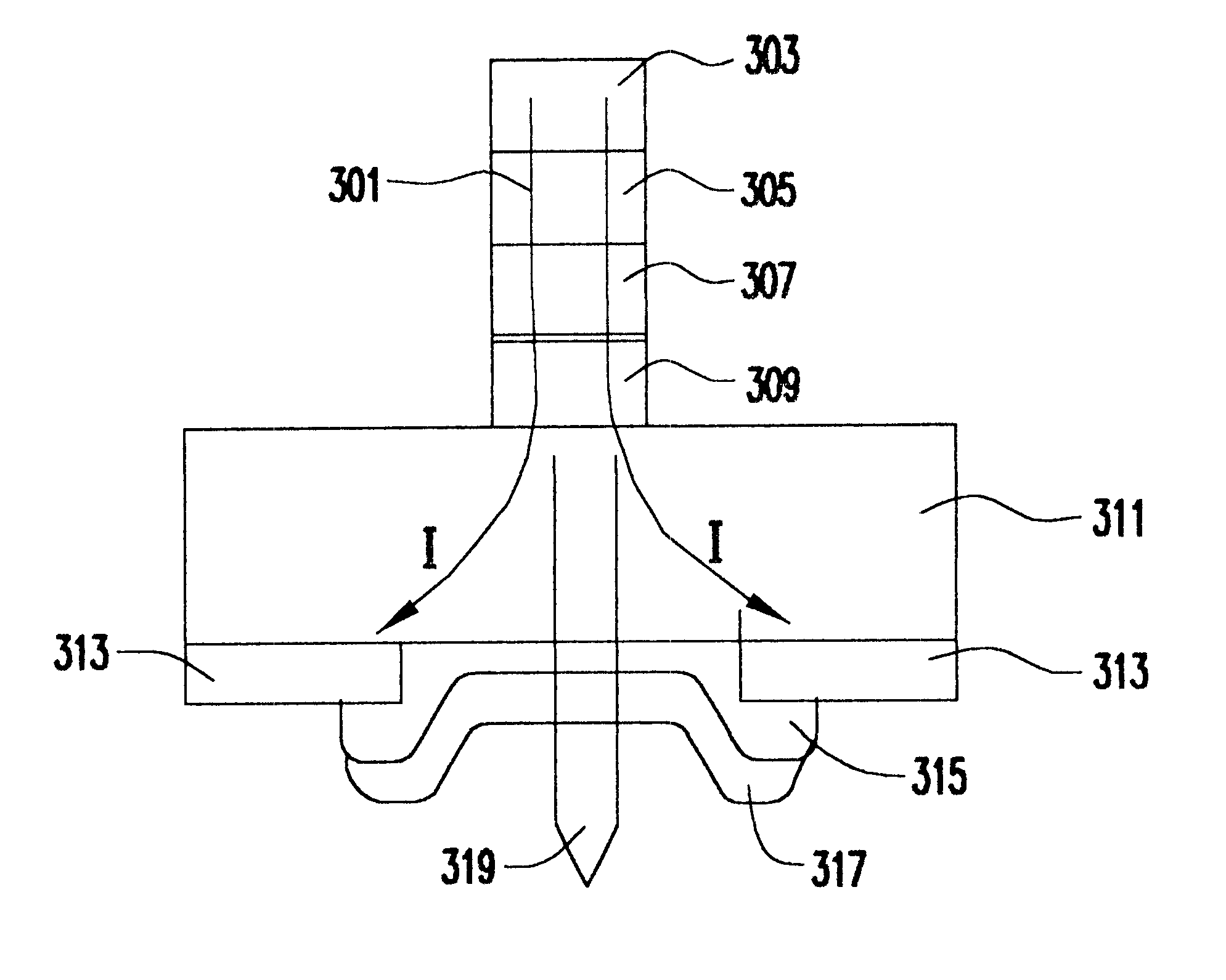
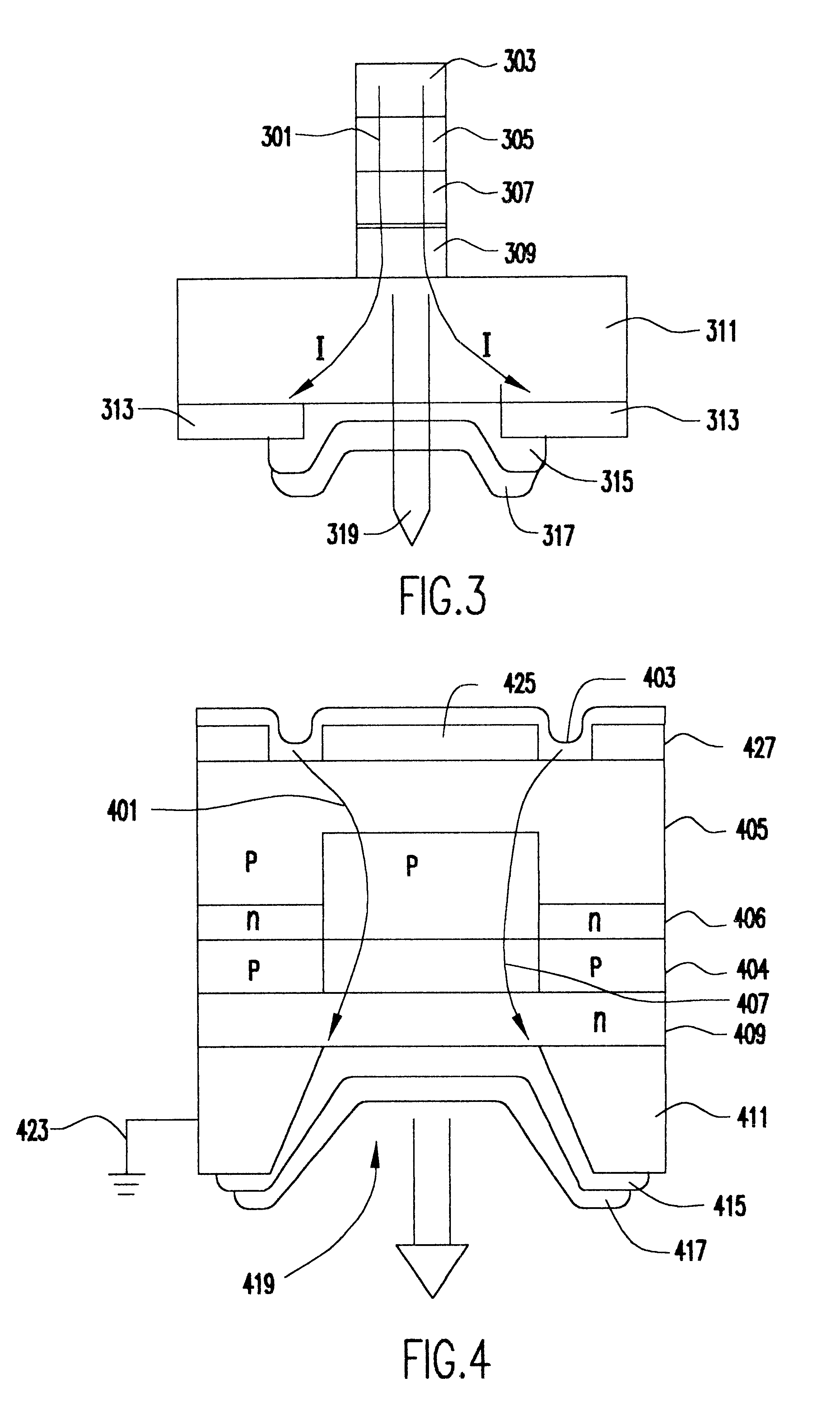
The present invention employs a variable reflectivity mirror to increase the amount of available output power. Such a mirror may be implemented by using a superconducting material for the mirror. A superconducting mirror has a reflectivity of one in the superconducting state. The reflectivity of a superconducting mirror may be lowered by causing it to enter a non-superconducting state. A superconductor can be made to enter a non-superconducting state by raising its temperature using a switched heating element, an applied magnetic field using a switched coil, or a switched current to raise the operating condition above a critical level. The superconducting state can be reentered by lowering the temperature, the applied magnetic field, or current below the critical level.

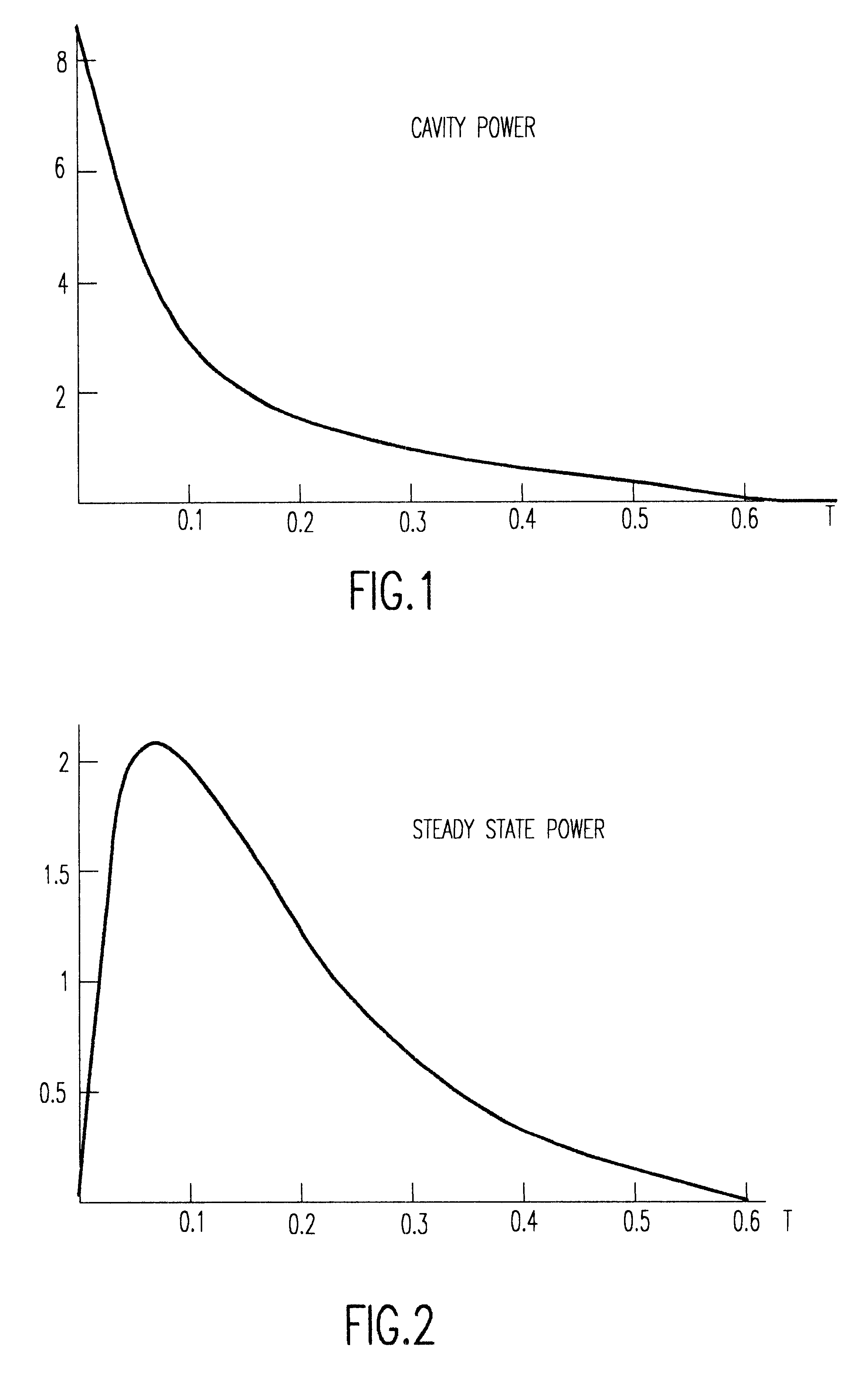
With the present invention, when the mirror is in the superconducting state, the reflectivity is one and energy is amplified and built up in the cavity. When optical output is desired, the mirror is caused to enter it...


PUM


Abstract

Output for a laser is greatly increased by altering the transmitivity of a superconductor layer which serves as one of the mirrors of the laser cavity. The superconductor layer is switched between a superconductive state, having reflectivity of one, and a non-superconductive state, having a reflectivity of less than one. When the mirror is in its superconducting state, output power is decreased and power in the cavity is increased, and when the mirror is in its non-superconducting state, output power of the laser is increased and power in the cavity decreases.

Description

1. Field of the InventionThe present invention generally relates to lasers and, more particularly, to a new laser construction that produces an output power pulse that greatly exceeds the previous optimal power of the prior art.2. Background DescriptionLasers consist of an optical cavity that provides feedback and a gain medium that provides optical amplification. Previously, lasers have used mirrors (dielectric or metallic) to build the optical cavity, such as a Fabry-Perot oscillator. Unfortunately, these mirrors have a fixed reflectivity. This necessitates choosing the reflectivity of the mirror to balance the amount of output coupling against the amount of feedback.Losses in a laser can be grouped into two different categories: a) non-useful losses due to diffraction, scattering, and absorption; and b) useful loss due to coupling of output power through a partially transmissive mirror. It is obvious that optical output power is maximized by minimizing the first group of losses. ...

Claims


Application Information

Patent Timeline
Patent Type & Authority Patents(United States)
IPC IPC(8): H01S5/00H01S5/183H01S5/028
CPCH01S5/18305H01S5/0207H01S5/0285H01S5/0425H01S5/2063H01S5/18308H01S5/18394H01S5/0614H01S5/18375H01S5/18377H01S5/04253H01S5/04254
Inventor PUZEY, KENNETH A.
Owner TERRACOMM RES
Why Eureka
Try Eureka