Thermoelectric cooling device using heat pipe for conducting and radiating

a technology of heat pipe and thermoelectric cooling device, which is applied in the direction of domestic cooling apparatus, lighting and heating apparatus, support, etc., can solve the problems of limited heat conducting area, difficult manufacturing, and significant reduction of heat conducting capacity, and achieve high efficiency and large area heat conduction and dispersion

Inactive Publication Date: 2002-03-05
LUQUAN JIWEI ELECTRICAL APPLIANCE
View PDF9 Cites 45 Cited by
  • Summary
  • Abstract
  • Description
  • Claims
  • Application Information

AI Technical Summary

Benefits of technology

An object of the present invention is to provide a thermoelectric cooling device that uses a heat pipe to conduct and disperse heat and applies evaporation and condensation (phase change) to absorb and discharge heat, so that achieves a high efficient and large area heat conduction and dispersion.

Problems solved by technology

Because of having heat resistance, the efficient heat conducting area is limited within a circle centered at the hot source and having a radius of 150 mm-180 mm.
Outside this area, the heat conducting capability reduces significantly.
Thus, it is difficult to manufacture and easy to get leaking and corrosion during the installation.
The heat exchange coefficient of this type can be as high as 150-1000 w / (m.sup.2 k), however, a corresponding water supply and a water pump is necessary, the application is thus limited.
In a heat dispersing member that utilizes principle of the heat from melting, the heat from solving and heat capacity of the materials, the disadvantages are resulted from the corrosion of the conducting components, the non-continuity and the instability of the heat discharging therefore, this type of the heat dispersing is not used widely.

Method used


Image

  • Thermoelectric cooling device using heat pipe for conducting and radiating
  • Thermoelectric cooling device using heat pipe for conducting and radiating
  • Thermoelectric cooling device using heat pipe for conducting and radiating

Examples


example 1

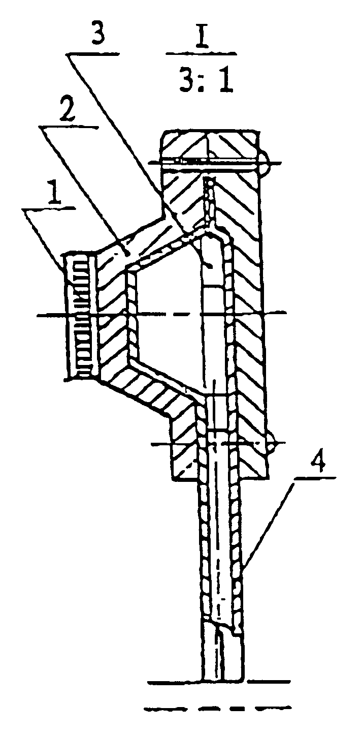
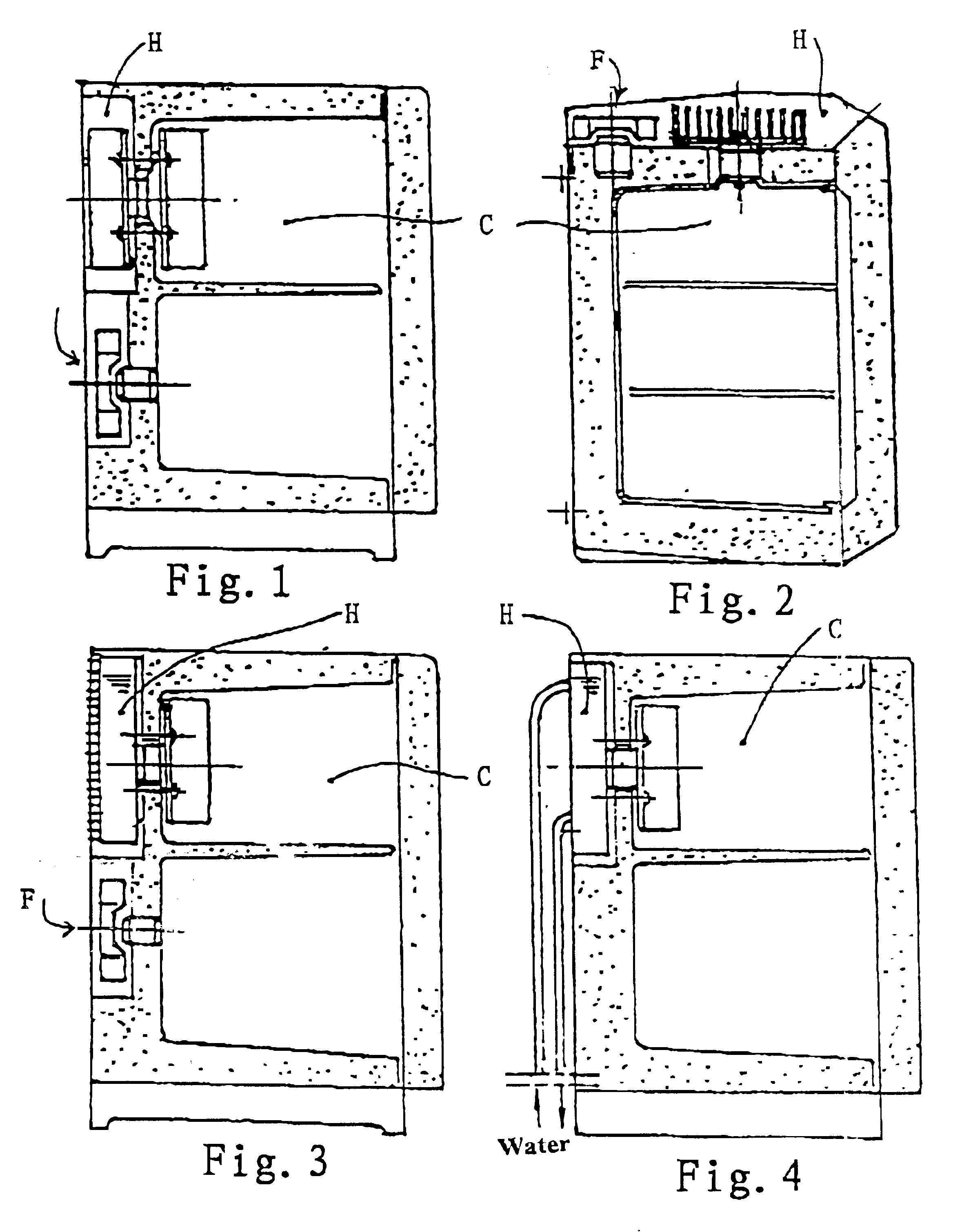
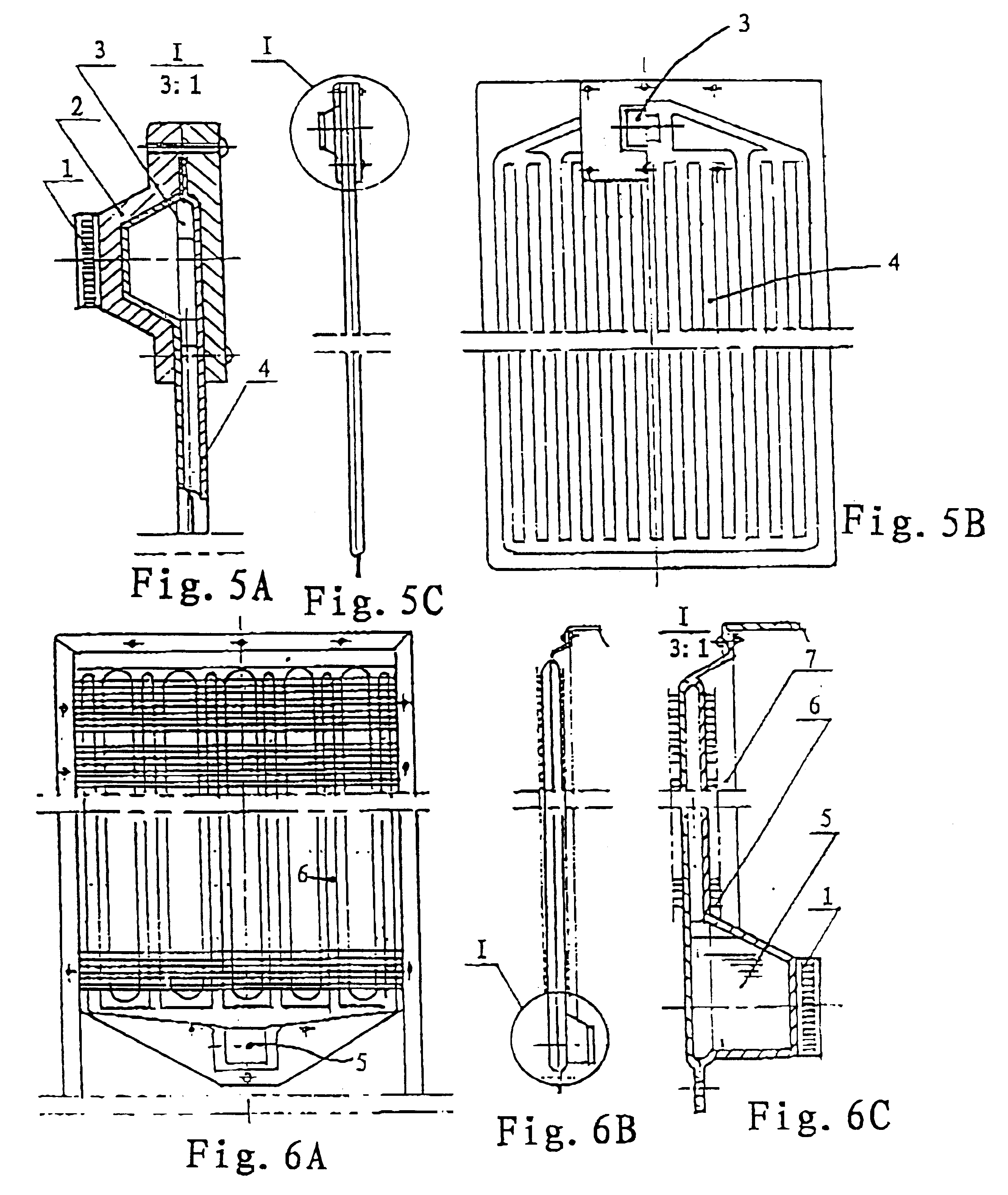
This is a device used for a room refrigerator. A gravitational heat pipe is used (see FIG. 8). The heat-pipe conducting plates that are formed by the blow-expending processes are used on the cold end. The heat-pipe radiator 6 that has a multi-bundle of tubes with the fin stripes is used on the hot end.

example 2

This is a device used for a vehicle-carried refrigerator. A cored heat pipe is used (see FIG. 9). The heat-pipe conducting plate 4 is formed by a hot-pressing and blow-expanding process. The hot end is provided with a heat-pipe radiator 6 that has a multi-bundle heat pipes with liquid-absorbing core inside and the finned strips on outside surface. The working medium inside this cored heat pipe can be returned to the heating end by the capillary force without the influence of the gravity. More area of the heat pipe can be obtained on the heating end in order to compensate weakness existing on the structure of the device.

example 3

This is a device used for a freezer. It is a thermoelectric cooling device using the osmotic-pressure heat pipe for heat conducting and dispersing (see FIG. 10). The cold end adopts a heat-pipe cold-conducting plate which is formed by a hot-pressing and blow-expanding process. The hot end is provided with a heat exchanger having osmotic-pressure heat-pipes. This kind of the heat pipe can utilize a pressure difference between two sides of the osmotic membrane to pump the condensed working medium from the lower cooling section to the higher heating section. Therefore, the cooling pipe can be lowered down for the maximum utilization of the heat dispersing space. It is more of practicability and flexibility in arrangement of the structure of the device.


PUM


Abstract

A thermoelectric cooling device using heat pipes for heat conducting and dispersing, comprising a multi-bundle of the heat pipe conducting plates installed at the cold end of the thermoelectric cooling member and converged to condenser, a multi-bundle of the heat pipe heat exchangers installed at the hot end of the thermoelectric cooling member with fin plates or fin stripes and converged to the evaporator. It performs a fast cooling and heat dispersing by heat pipes and high efficient phase change and heat transport of the working medium. It can eliminate the heat exchange produced by the heat accumulation on the cold and hot ends, so as to run at the minimum operation temperature differences in order to obtain the maximum cooling capacity.

Description

FIELD OF THE PRESENT INVENTIONThe present invention relates to a technique and an equipment for the thermoelectric cooling, in particular, to a heat conducting and dispersing equipment used in the thermoelectric cooling device.PRIOR ARTThe thermoelectric cooling is a benefit of the so-called Peltier effect which utilizes the potential change of the electrons and the holes in a circuit including two dissimilar conductors, and the phenomenon of the heat absorption and discharge which produces a hot end and a cold end, to perform cooling (or heating) functions. Since there is a current flowing through the thermocouple during operation of the cooler, the Joule heats will be created, at the same time, the temperature at the hot end tends to expand to the cold end, thus at a thermal equilibrium situation, the equilibrium equation will be as follows:Q.sub.c =a.sub.pn T.sub.c I-0.5I.sup.2 R-K(T.sub.n -T.sub.c)That is, the amount of cooling at the cold end is equal to the Peltier cooling eff...

Claims


Application Information

Patent Timeline
Patent Type & Authority Patents(United States)
IPC IPC(8): F25B21/02F25D25/02F25D11/02F25B25/00F25B23/00F28D15/02
CPCF25B21/02F28D15/0233F28D15/0266F25B23/006F25B25/005F25D11/02F28F2210/02F25D2400/10F25D2400/28F25D25/028
Inventor GUO, CHENGAO, JUNLINGZHANG, AIMIN
Owner LUQUAN JIWEI ELECTRICAL APPLIANCE
Why Eureka
Try Eureka