Air conditioning apparatus with air-temperature adjustment

a technology of air-temperature adjustment and air-conditioning equipment, which is applied in the direction of temperatue control, process and machine control, instruments, etc., can solve the problems of delay in temperature-changing response delay for users, inability to immediately reduce the temperature of blown-air, and large delay in the actual temperature of air blown into the passenger compartmen

Inactive Publication Date: 2002-03-05
DENSO CORP
View PDF13 Cites 20 Cited by
  • Summary
  • Abstract
  • Description
  • Claims
  • Application Information

AI Technical Summary

Problems solved by technology

However, in the hot-water flow adjustment method, in a case where the temperature of blown-air is in a low-temperature area (i.e., cooling side area), when a user (passenger) further operates a temperature adjustment operation member of an air conditioning panel toward a low-temperature side, the temperature of blown-air is not immediately reduced even when the flow amount of hot water is reduced by reducing an opening degree of a hot water valve.
That is, a change of actual temperature of air blown into the passenger compartment is greatly delayed as compared with a temperature-changing operation of the user.
Therefore, a temperature-changing response delay for the user may be caused.
However, when the opening degree of the hot water valve is throttled to a little opening degree, a pressure difference between hot water before flowing into the hot water valve and after flowing through the hot water valve becomes larger, a flow rate of hot water passing through a throttle portion of the hot water valve becomes faster, and water-flowing noise is increased.
However, because the max-cool door opens the cool air bypass passage only during the maximum cooling, the temperature of blown-air is not controlled in the other control area.
Thus, the same problem described above in the hot-water flow adjustment method may be caused.

Method used


Image

  • Air conditioning apparatus with air-temperature adjustment
  • Air conditioning apparatus with air-temperature adjustment
  • Air conditioning apparatus with air-temperature adjustment

Examples


case 11

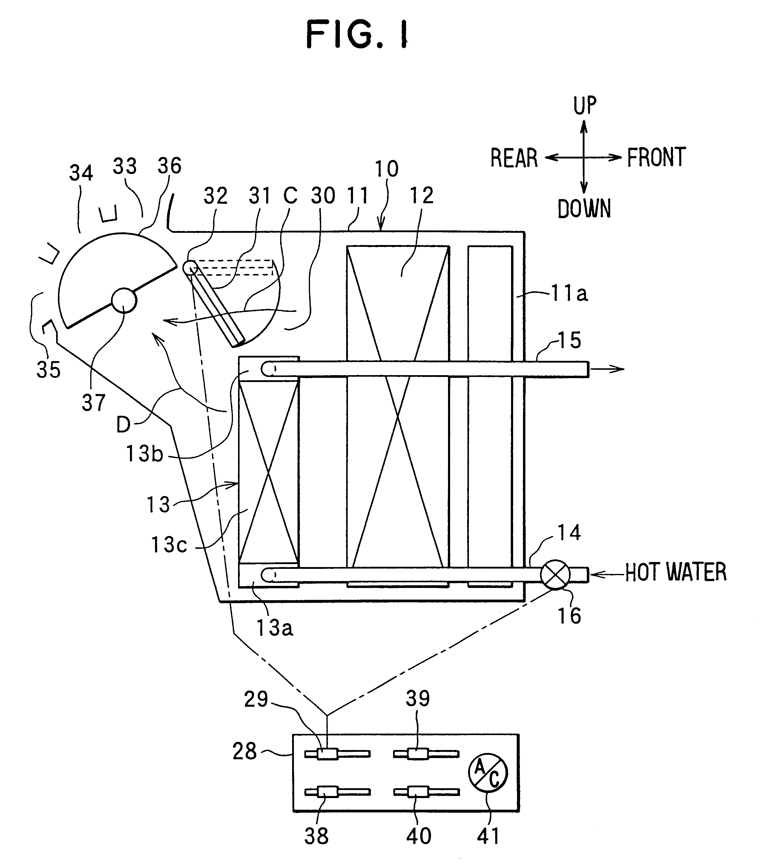
The air conditioning case 11 is made of resin which has an elasticity to some degree and is superior in a strength, such as polypropylene, and is composed of plural division case portions. Plural division case portions of the air conditioning case 11 are integrally connected by a fastening unit such as a metal spring clip and a screw, after the evaporator 12, the heater core 13 and components such as a door described later are accommodated therein, to construct the air conditioning unit 10.

The evaporator 12 is disposed within the air conditioning case 11 at a vehicle front side. The evaporator 12 is disposed in the air conditioning case 11 to cross an entire air passage within the air conditioning case 11. In a refrigerant cycle of the vehicle air-conditioning apparatus, refrigerant of the refrigerant cycle flows into the evaporator 12, and absorbs an evaporation-latent heat from air passing through the evaporator 12, so that air passing through the evaporator 12 is cooled.

An air in...

first embodiment

The heater core 13 of the first embodiment includes a hot-water inlet tank 13a disposed at a lower side, a hot-water outlet tank 13b disposed at an upper side, and a heat-exchanging core portion 13c between the hot-water inlet tank 13a and the hot-water outlet tank 13b. The heat-exchanging core portion 13 are integrally brazed after laminating plural flat tubes each of which is formed by connecting both flat metal plates and the plural corrugated fins.

Thus, the heater core 13 is a one-way flow type in which hot water from the hot water inlet tank 13a flows upwardly through the entire flat tubes from below. A hot water inlet pipe 14 is connected to the hot-water inlet tank 13a, and a hot water outlet pipe 15 is connected to the hot-water outlet tank 13b. Therefore, hot water circulates between a vehicle engine (not shown) and the heater core 13 through the hot water inlet and outlet pipes 14, 15.

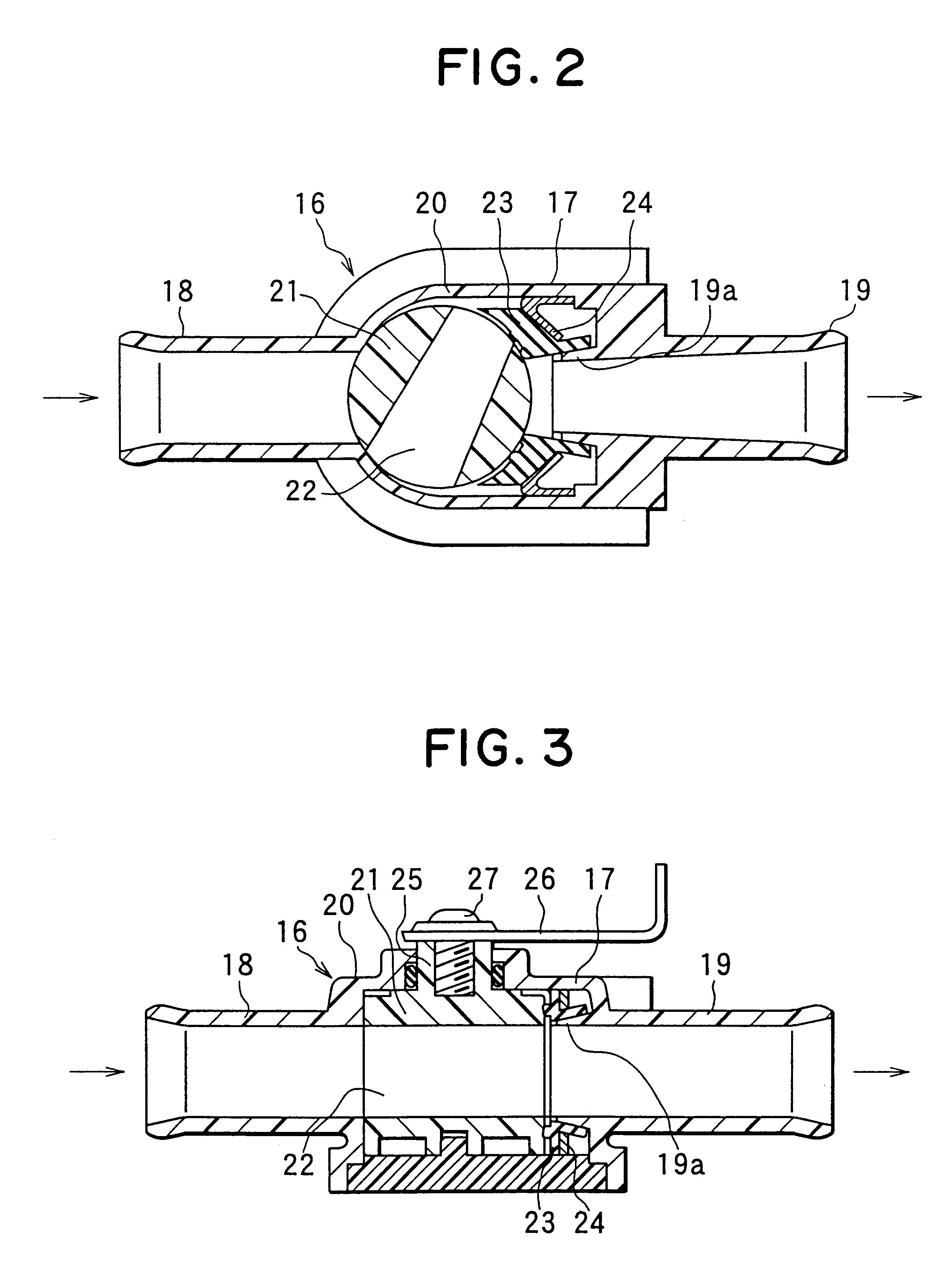
Further, a hot water valve 16 is disposed in the hot-water inlet pipe 14. The hot water v...

second embodiment

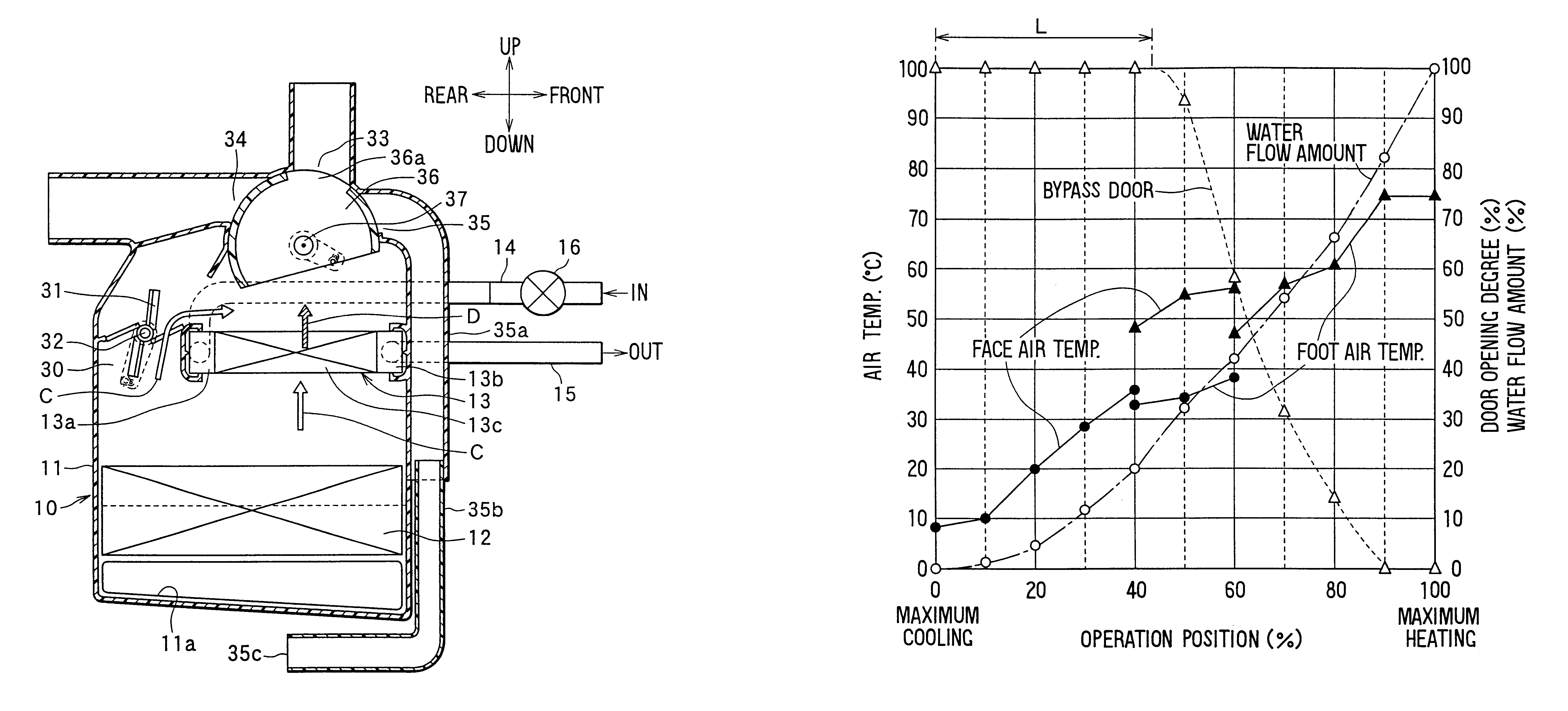
FIG. 9 shows the operatively linked characteristics of the hot water valve 16 and the cool air bypass door 31 according to the The horizontal axis in FIG. 9 indicates the operation position of the temperature-adjustment operation member 29. In the horizontal axis of FIG. 9, the maximum cooling position (the lowest-temperature position) where the hot water valve 16 is fully closed is set at 0%, and the maximum heating position (i.e., highest temperature position) where the hot water valve 16 is fully opened is set at 100%, and the operation position of the temperature-adjustment operation member 29 is indicated by percentages. Further, in the vertical axis of FIG. 9, both of the flow amount of hot water adjusted by the hot water valve 16 and the opening degree of the cool air bypass door 31 are indicated by percentages, and the temperature of air blown into the passenger compartment, adjusted by the hot water valve 16 and the cool air bypass door 31, is indicated.

In the second embod...


PUM


Abstract

A vehicle air conditioning apparatus includes a hot water valve for adjusting a flow amount of hot water flowing into a heating heat exchanger, a bypass passage through which air bypasses the heating heat exchanger, and a bypass door for opening and closing the bypass passage. In a high-temperature side area where temperature of air blown into the passenger compartment becomes higher, the temperature of air to be blown into the passenger compartment is adjusted by a hot-water flow adjustment of the hot water valve while the bypass door is operated at a fully closed position. On the other hand, in a low-temperature side area where temperature of air blown into the passenger compartment becomes lower, the temperature of air to be blown into the passenger compartment is adjusted by combining the hot-water flow adjustment of the hot water valve and the air flow adjustment of the bypass door. Thus, even in a minute flow area of hot water flowing into the heating heat exchanger, the temperature of air blown into the passenger compartment is accurately adjusted.

Description

This application is related to and claims priority from Japanese Patent Applications No. Hei. 11-27864 filed on Feb. 4, 1999, and No. Hei. 11-315555 filed on Nov. 5, 1999.1. Field of the InventionThe present invention relates to a vehicle air conditioning apparatus which adjusts temperature of air blown into a passenger compartment by combining a hot water valve for adjusting a flow amount of hot water flowing into a heating heat exchanger and a cool air bypass door for adjusting a cool air amount bypassing the heating heat exchanger.2. Description of Related ArtIn an air mixing method of a conventional air conditioning apparatus described in U.S. Pat. No. 5,893,407, a ratio between an amount of cool air bypassing a heating heat exchanger and an amount of warm air passing through the heating heat exchanger is adjusted by an air mixing door, so that temperature of air blown into a passenger compartment is adjusted.On the other hand, in a hot-water flow adjustment method, an amount of...

Claims


Application Information

Patent Timeline
Patent Type & Authority Patents(United States)
IPC IPC(8): B60H1/00B60H1/32
CPCB60H1/0005B60H1/00814B60H2001/00171
Inventor SHIBATA, KAZUJIKAMIYA, TOMOHIRO
Owner DENSO CORP
Why Eureka
Try Eureka