Method and device for separating particles from an electrically conductive liquid flow using electromagnetic forces

a technology of electromagnetic force and separation method, applied in the direction of discharge device, solid separation, blast furnace, etc., can solve the problem of preventing polluting solids no more than preventing them

Inactive Publication Date: 2002-03-12
CENT NAT DE LA RECHERCHE SCI
View PDF2 Cites 35 Cited by
  • Summary
  • Abstract
  • Description
  • Claims
  • Application Information

AI Technical Summary

Problems solved by technology

Although in some ways this type of process improves the quality of the cast metal, it does no more than pr...

Method used


Image

  • Method and device for separating particles from an electrically conductive liquid flow using electromagnetic forces
  • Method and device for separating particles from an electrically conductive liquid flow using electromagnetic forces
  • Method and device for separating particles from an electrically conductive liquid flow using electromagnetic forces

Examples


Embodiment Construction

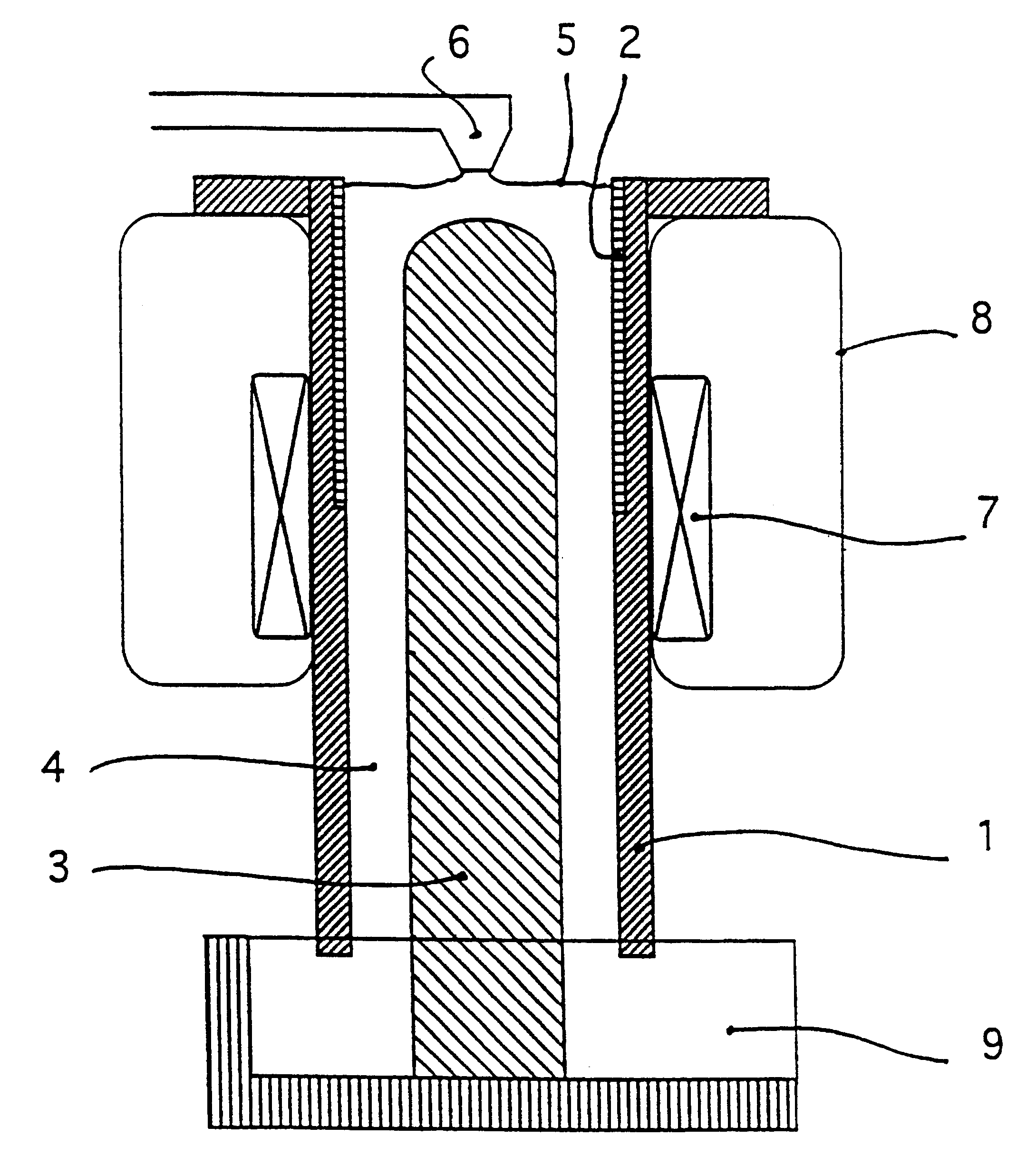
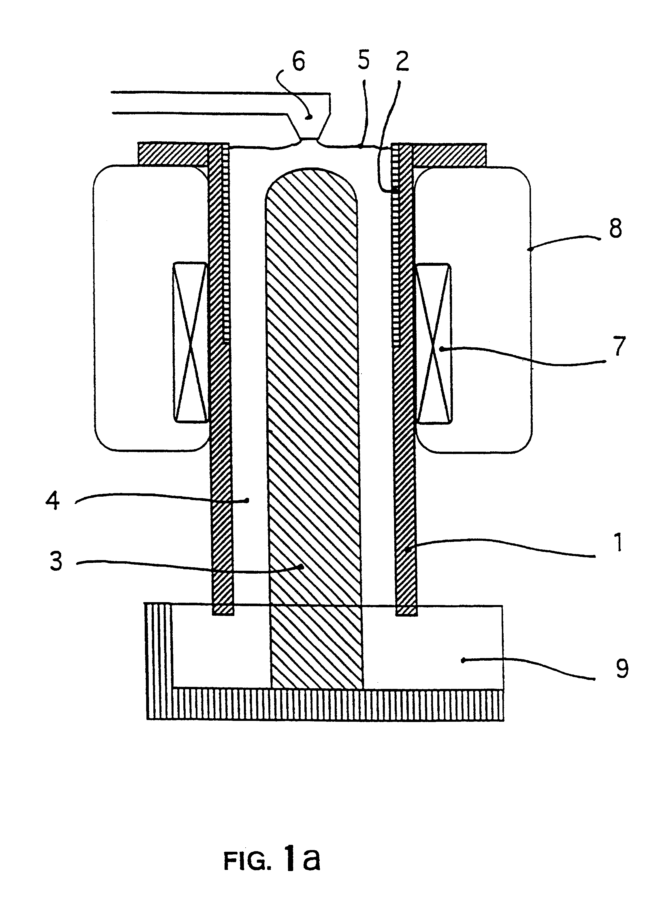
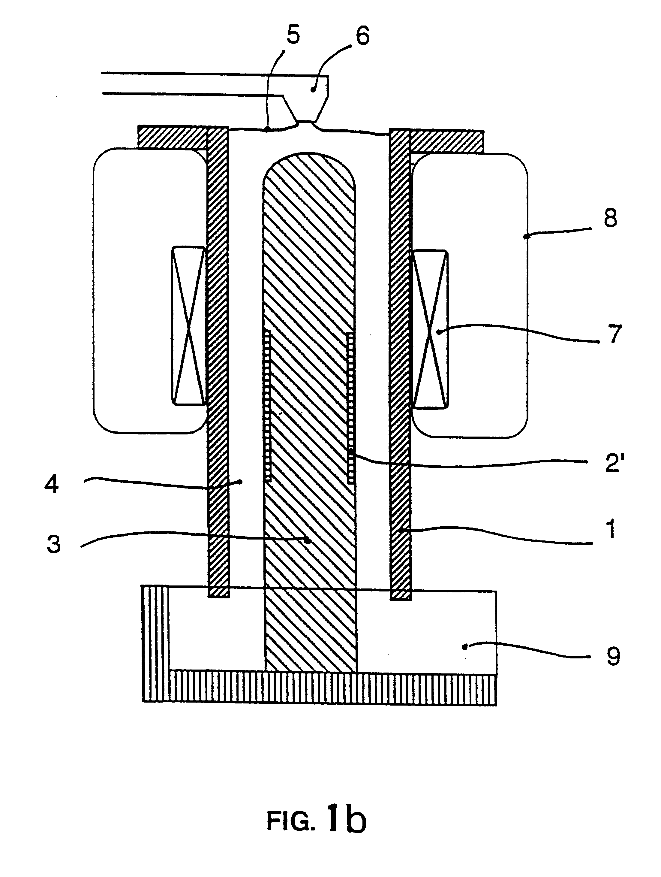
A first aspect of the invention is a process for separation of inclusions contained in an electricity conducting liquid stream, the inclusions and the liquid having different electrical conductivities, by means of electromagnetic forces characterized in that the said flow is subjected to a heterogeneous magnetic flux in space, the said magnetic flux resulting from a continuous static magnetic field.

The process can thus deviate all inclusions in the same direction, generally radial within the moving liquid and usually confined within an appropriate chamber so that they can be concentrated in a part of the stream (usually near the boundary) and then recovered from this area, the rest of the flow thus being free of inclusions.

The process is applicable to all liquid metals including steel, copper, etc.), but particularly to Light metals or liquids such as aluminum, magnesium, sodium and their alloys, and to aqueous saline solutions, molten salts, etc., when their low density does not ha...


PUM

PropertyMeasurementUnit
Lengthaaaaaaaaaa
Electrical conductivityaaaaaaaaaa
Magnetic fieldaaaaaaaaaa

Abstract

A method for separating inclusions from an electrically conductive liquid flow using electromagnetic forces, wherein the inclusions and the liquid have differing electrical conductivities. The flow is exposed to a spatially heterogeneous magnetic flux produced by a continuous static magnetic field.

Description

TECHNICAL DOMAINThe domain of this invention relates to the separation of immiscible inclusions (solids, liquids, gasses) contained in a stream of electricity conducting liquid, the particles having a different electrical conductivity to to that of the liquid, by means of electromagnetic forces obtained by means of a static magnetic field, and particularly inclusions contained in a liquid metal stream such as aluminum.STATE OF THE ARTPatent FR 2614801 describes a process for separation of inclusions contained in a liquid metal that consists of applying a field of electromagnetic forces to a filter medium (for example a porous mass, gravel bed, filter plug, etc.) through which the liquid metal passes, the electromagnetic forces being obtained:either by means of a DC current passing through the liquid metal being filtered and directed parallel to the liquid metal flow; the electromagnetic forces causing migration of inclusions towards the walls delimiting the pores of the filter mediu...

Claims


Application Information

Patent Timeline
IPC IPC(8): B03C1/035B03C1/23B03C1/02C22B9/02C22B21/06C22B21/00
CPCB03C1/035C22B21/066C22B9/023B03C1/23Y02P10/20
Inventor PILLIN, BEATRICEGILLON, PASCALEBEAUGNON, ERIC
Owner CENT NAT DE LA RECHERCHE SCI
Why Eureka
Try Eureka