
System for retrieving a gas phase sample from a gas stream containing entrained liquid, and sample conditioner assembly therefore

a technology of gas phase and entrained liquid, which is applied in the field of system for retrieving gas phase samples from gas streams containing entrained liquid, and the assembly of sample conditioners is used in sampling, instruments, measurement devices, etc., can solve the problems of coalesced liquid presenting serious problems, no provision for maintaining process source gas temperature, and almost impossible to follow the recommended practices, etc., to prevent the change of gas phase composition and cost effective high accuracy

Inactive Publication Date: 2002-03-19
MAYEAUX HLDG
View PDF2 Cites 49 Cited by
  • Summary
  • Abstract
  • Description
  • Claims
  • Application Information

AI Technical Summary

Benefits of technology

Unlike the prior art, the present, searched for invention provides a system for retrieving a gas phase sample from a gas stream containing entrained liquid, in a cost effective highly accurate, and generally easily implemented fashion, providing a gas sample at the prevailing process gas source pressure and temperature condition, thereby preventing gas phase composition changes. The subject invention, a sample conditioner assembly, provides a coalescer design that overcomes the problems associated with prior art systems, methods, and hardware.
Lastly, it is an object of the present invention to provide a method for accurately sampling a gaseous hydrocarbon stream having entrained liquid therein, in order to accurately discern the properties thereof.

Problems solved by technology

Following the recommended practices has been almost impossible due to lack of available hardware to accomplish the task.
Furthermore, there is no provision for maintaining process source gas temperature.
With increasing environmental concerns disposal of the coalesced liquid can present serious problems if it cannot be returned to the original source.

Method used


Image

  • System for retrieving a gas phase sample from a gas stream containing entrained liquid, and sample conditioner assembly therefore
  • System for retrieving a gas phase sample from a gas stream containing entrained liquid, and sample conditioner assembly therefore
  • System for retrieving a gas phase sample from a gas stream containing entrained liquid, and sample conditioner assembly therefore

Examples


first embodiment

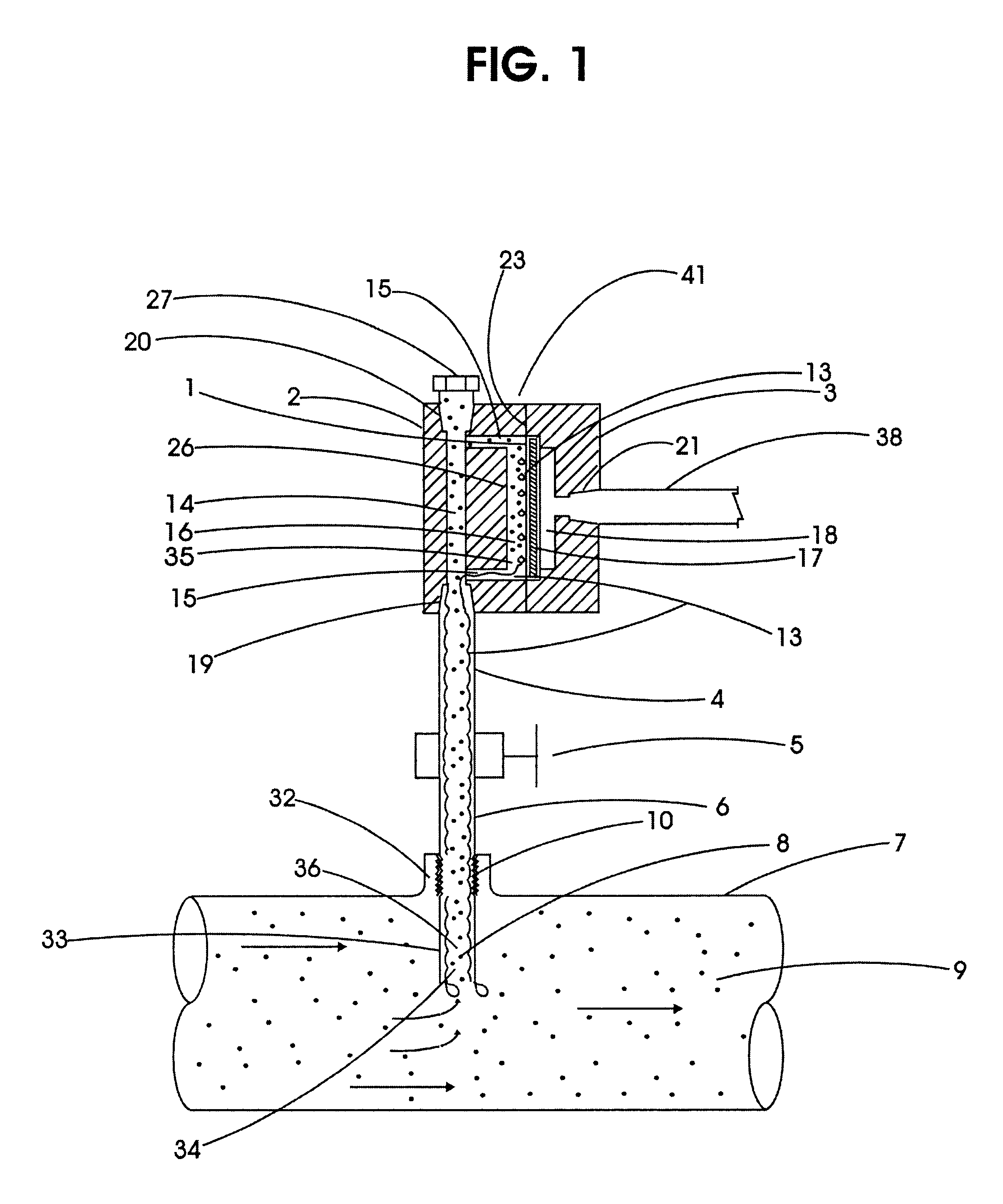
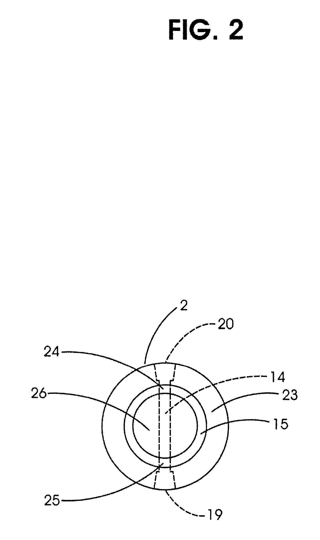
Referring to FIGS. 1 and 2, the preferred, first embodiment of the invention contemplates a sample conditioning assembly 41, utilizing a circular sheet of phase separation membrane 1, inlet plate 2, and outlet plate 3, sample conduit 4, block valve 5, sample conduit 6, membrane support 17, and sample conduit 38.

A passage 14, located in inlet plate 2, extends between port 19 and port 20. A circular groove 15, in the outer face 23 of inlet plate 2, intersects passage 14 at point 24 and point 25. Membrane retention plate 26, formed on face 23 of inlet plate 2 is circumscribed by circular groove 15. Port 19, Port 20 and Port 21 are threadingly adapted for receiving sample conduit 4, sample conduit 38, and plug 27.

A segment 10 of sample conduit 6 is threadingly adapted for attachment to threaded member 32 located on containment wall 7 of process gas source 9. Block valve 5 is in series fluid communication with sample conduit 4 and sample conduit 6. Sample conduit Segment 33 of sample con...

third embodiment 106

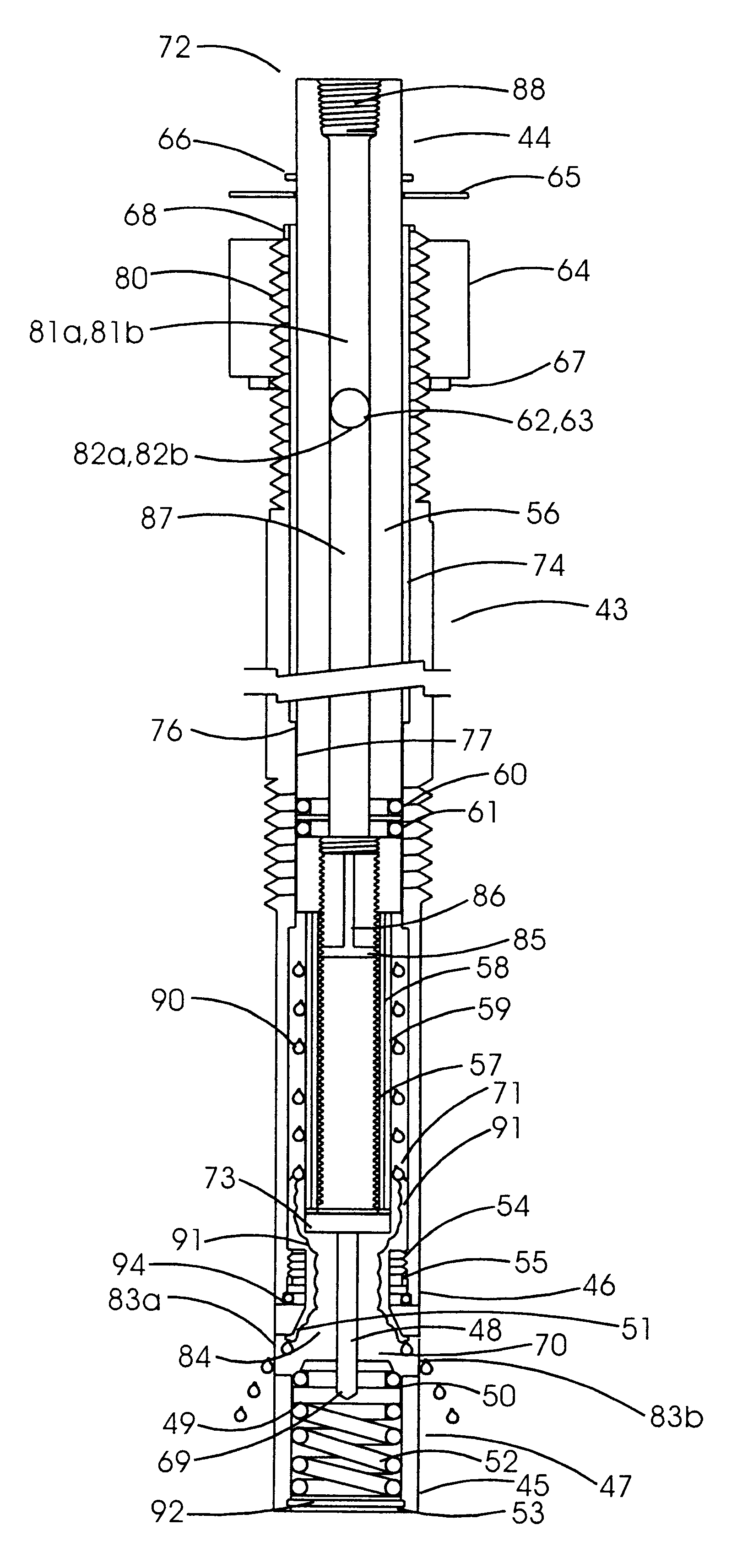
the present invention (Refer to FIG. 13 and FIG. 14) is comprised of aforementioned housing assembly 43 and coalescing / pressure reducing assembly 95. Said coalescing / pressure regulator assembly 95 is comprised of tubular stem 96, rod 97, ball 98, spring 99, nut 107, lower housing 100, upper housing 101, diaphragm 102, spring 103, and handle 105, retaining bolt 57, washer 65, membrane support 58, phase separating membrane 59, O ring 60, O ring 61, rod 62, rod 63, right threaded nut 64, and thrust washer 67. In addition to the coalescing and entrained liquid removal function provided by second embodiment 72, said third embodiment 106 provides the additional function of pressure regulation.

second embodiment

A small slip stream of process source gas 78, at process gas source pressure and made free of entrained liquid by the second embodiment coalescing process previously described, exits passage 86 thru a center hole in nut 107, enters spring cavity 108, flows between ball 98 and seat 110, passage 112, then thru annulus 109 formed by the outer diameter of rod 97 and inner diameter of cavity 113 of tubular stem 96, enters diaphragm cavity 114 and then exits by flowing thru passage 115, port 116, and conduit 117 thereon to an external analyzer or sample storage means not shown.

The pressure of sample gas in diaphragm cavity 114 acting against diaphragm 102 produces an upward force against spring 103. The decompression of spring 52 produces an upward force against ball 98, lower rod segment 111, and rod 97 which serves to maintain contact between rod 97 and diaphragm 102. Handle 105 has a right threaded member 104 which is threadingly engaged in female threads 118. The gas pressure in passa...


PUM


Abstract

A system for the retrieval and initial conditioning of sample gas for "on line" analyzers or filling of gas sample cylinders. The preferred embodiment of the present invention contemplates a system configured to obtain a representative gas phase sample from a process gas containing entrained liquid, or a process gas which generally is highly susceptible to partial condensation of some gas phase components. The preferred embodiment of the present invention teaches an assembly including a phase separation membrane and housing configured to facilitate the removal of entrained liquid from a sample gas stream. Accuracy of the sample is enhanced, and compositional changes are avoided by first extracting a sample from the process gas followed by removal of entrained liquid it may contain, with the entrained liquid removal being conducted at the prevailing process gas pressure and temperature. Thereafter the liquid free sample may be desaturated by lowering its pressure to reduce its susceptibility to condensation.

Description

The present invention relates to the sampling of process fluids such as implemented by petrochemical plants, refineries, gas separation plants, natural gas pipelines, etc, and in particular to the collection and initial conditioning of sample gas for "on line" analyzers or filling of gas sample cylinders.The preferred embodiment of the present invention contemplates a system configured to obtain a representative gas phase sample from a process gas containing entrained liquid, or a process gas which generally is highly susceptible to partial condensation of some gas phase components.The preferred embodiment of the present invention teaches an assembly including a phase separation membrane and housing configured to facilitate the removal of entrained liquid from a sample gas stream. Accuracy of the sample is enhanced, and compositional changes are avoided by first extracting a sample from the process gas followed by removal of entrained liquid it may contain, with the entrained liquid...

Claims


Application Information

Patent Timeline
IPC IPC(8): G01N1/20G01N35/08G01N35/00
CPCG01N1/2035G01N1/4005G01N35/08G01N2035/00326G01N33/22
Inventor MAYEAUX, DONALD P.
Owner MAYEAUX HLDG
Learn More