Photodiode transimpedance circuit

a technology of photodiodes and transimpedance circuits, applied in the field of improved transimpedance circuits, can solve the problems of weak signals, no gain control, severe signal distortion or even complete signal loss,

Inactive Publication Date: 2002-03-19
SILICON LAB INC
View PDF22 Cites 38 Cited by
  • Summary
  • Abstract
  • Description
  • Claims
  • Application Information

AI Technical Summary

Benefits of technology

FIG. 8 is a circuit diagram illustrating an example of the differential front end circuit of...

Problems solved by technology

However, the circuit shown in FIG. 1 has no gain control.
On strong signals, the transimpedance amplifier 10 will overload causing severe signal distortion or even complete loss of the signal received by photodiode 20.
In addition, because this circuit has no automatic gain control (AGC) capability, even strong signals can be disrupted by weak interference in the signal periods between data pulses.
Although this fro...

Method used


Image

  • Photodiode transimpedance circuit
  • Photodiode transimpedance circuit
  • Photodiode transimpedance circuit

Examples


Embodiment Construction

The present invention relates to an improved photodiode receiver front end that has the characteristics of low noise, wide bandwidth, large ambient direct current (DC) current correction, and large gain control range.

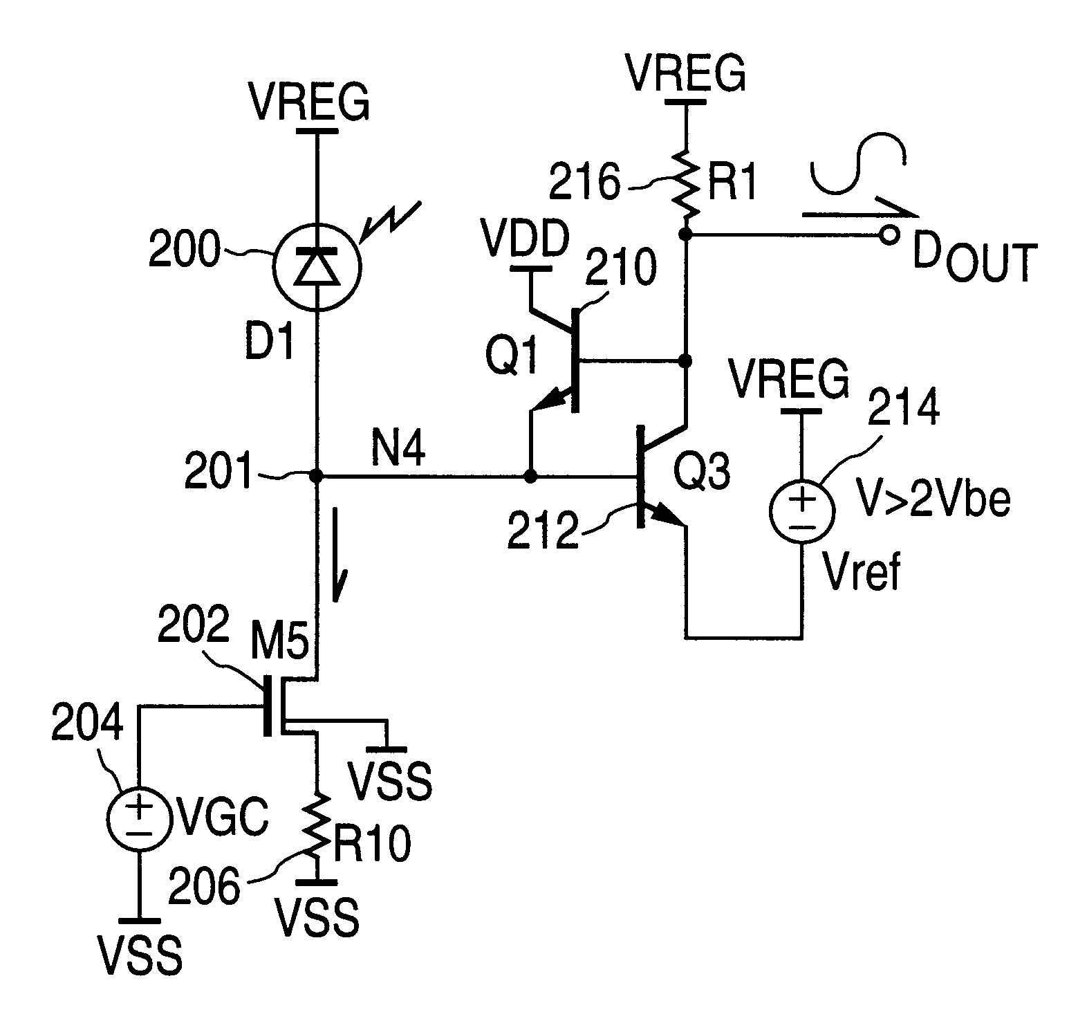
FIG. 4 is a circuit diagram illustrating one embodiment of an infrared front end circuit according to the present invention. FIG. 4 shows the basic structure of the present transimpedance front end having a base of transistor 210 coupled to a collector of transistor 212, an emitter of transistor 210 coupled to a base of transistor 212. In this embodiment, the cathode of photodiode 200 is returned to a high side regulated supply called VREG. Reference voltage VREF is also returned to VREG since it provides an amplifier AC reference for a transimpedance amplifier formed by transistors 210 and 212 that amplifies the signal received at circuit node 201 and outputs an amplified received signal at DOUT. In this embodiment of the present invention, photodiode 200 modulates a c...


PUM


Abstract

Disclosed is a front end circuit involving a transimpedance amplifier that drives a resistor, thereby lowering the input impedance of the circuit by dividing the feedback resistance by the gain of the amplifier. In the front end circuit of the present invention, a first transistor is coupled in series with a resistor, where the received signal is input to a base or gate of the first transistor and the amplified received signal is recovered from a collector or drain of the first transistor such that the first transistor and resistor provide the gain of the front end circuit. A second transistor has an emitter or source coupled to the base or gate of the first transistor. A base or gate of the second transistor is coupled to the collector or drain of the first transistor and a collector or drain of the second transistor is coupled to a power supply rail. The second transistor thus provides the feedback path for the transimpedance amplifier thereby reducing the input impedance of the circuit.

Description

1. Field of the InventionThe present invention is directed toward an improved transimpedance circuit for use in receiving a communications signal.2. Description of the Related ArtInfrared receivers have become popular and useful devices for short range wireless communication of both analog and digital signals. Due to the high volume and widespread utilization of these receivers, competitive pressures have made it increasingly important that these receivers have optimum performance at low cost.The Infrared Data Association (IrDA) organization has defined a new infrared protocol called IrDA Control (IrCtrl) that is intended for sending two-way short packet, control information for in room, very high volume consumer electronic appliance and video game applications. (See www.irda.org for further information regarding IrDA standards). Smarter two-way IrCtrl transceivers may eventually replace conventional very high volume one-way remote controls, allowing consolidation of several individ...

Claims


Application Information

Patent Timeline
IPC IPC(8): H03F3/08H03F3/04
CPCH03F3/082
Inventor COLACO, STEPHEN F.
Owner SILICON LAB INC
Why Eureka
Try Eureka