
Energy trapping type piezoelectric filter with a shielding conductive member on a bottom insulating base plate upper surface

a piezoelectric filter and shielding technology, applied in piezoelectric/electrostrictive/magnetostrictive devices, piezoelectric/electrostriction/magnetostriction machines, electrical equipment, etc., can solve the problems of deteriorating inevitably forcing the piezoelectric substrate, and affecting the service life of the filter, so as to improve the attenuation characteristic of the filter

Inactive Publication Date: 2002-03-19
NGK SPARK PLUG CO LTD
View PDF6 Cites 19 Cited by
  • Summary
  • Abstract
  • Description
  • Claims
  • Application Information

AI Technical Summary

Benefits of technology

to provide an energy trapping type piezoelectric filter in which a coupling of an input and output electrodes is more reduced to improve an attenuation characteristic of the filter.
a shielding conductive member provided on an upper surface of the insulating base plate for preventing an electromagnetic coupling between the input electrode and the output electrodes, the shielding conductive member being connected to the ground electrodes.
With the provision of the shielding conductive member on an upper surface of the insulating base plate between the input / output electrodes, any coupling of the input / output electrodes can be effectively prevented, thereby improving an attenuation characteristic of the filter.
a shielding conductive member provided on an upper surface of the insulating base plate for preventing an electromagnetic coupling between the input / output electrodes, the shielding conductive member being connected to the ground electrode.

Problems solved by technology

Such a conventional arrangement, however, has disadvantages that the piezoelectric substrate inevitably is forced to have an oblong profile and the piezoelectric filter has to have a large surface area for carrying the components thereon.
Additionally, such a piezoelectric filter is subjected to various restrictions in terms of the profile, the thickness and the regions assigned to the oscillating sections to significantly limit the variable capacitance range, although the piezoelectric filter has only a single coupling capacitor.
Therefore, it will be apt to easily become electromagnetically coupled with each other to damage the attenuation characteristic of the device.
This results in a deterioration of an attenuation characteristic of the filter.
However, it has been found that an influence of a coupling of the output electrode and the input electrode outside of the bottom surface of the insulating base substrate is not negligible.

Method used


Image

  • Energy trapping type piezoelectric filter with a shielding conductive member on a bottom insulating base plate upper surface
  • Energy trapping type piezoelectric filter with a shielding conductive member on a bottom insulating base plate upper surface
  • Energy trapping type piezoelectric filter with a shielding conductive member on a bottom insulating base plate upper surface

Examples


Embodiment Construction

The present invention will now be described with reference to the accompanying drawings that illustrate preferred embodiments of the invention.

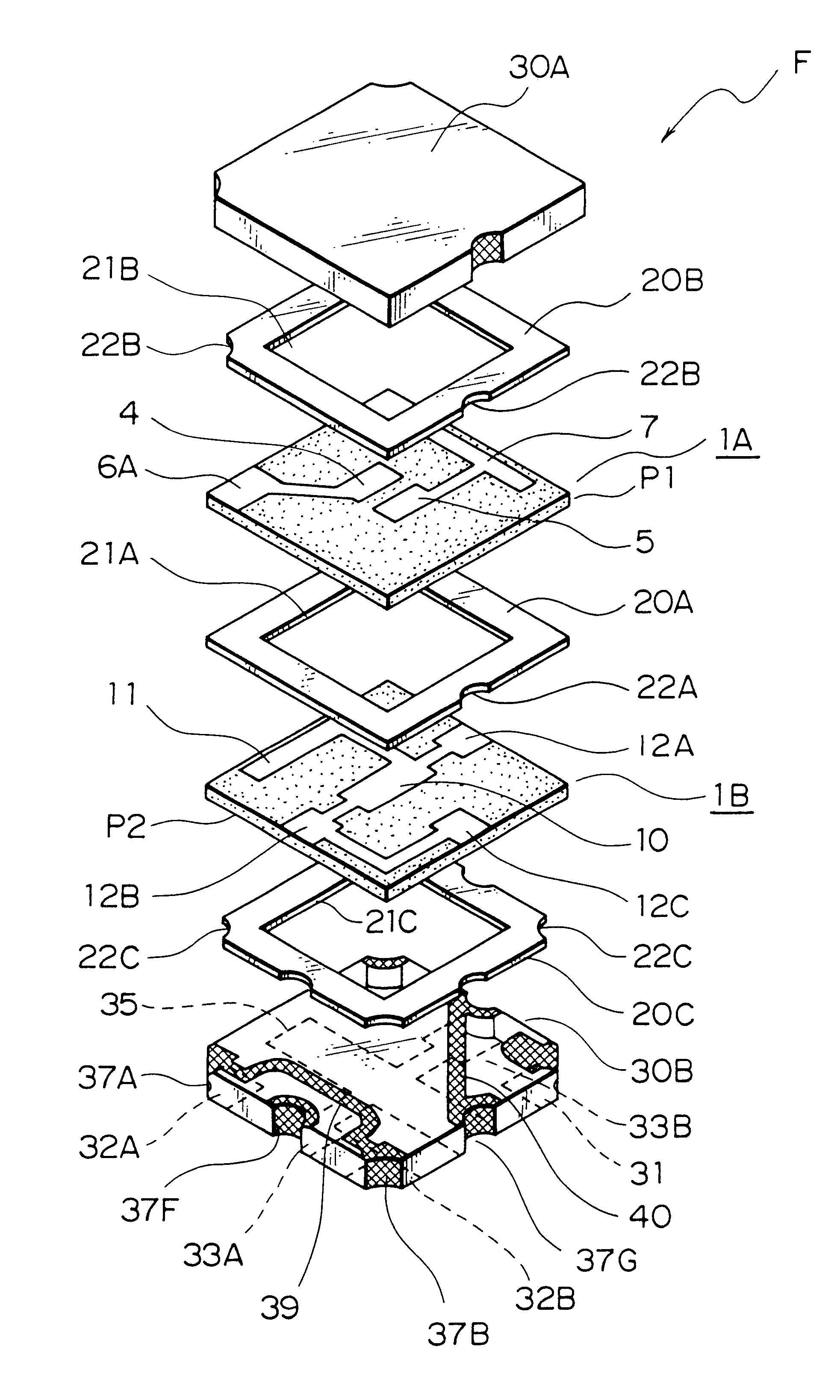
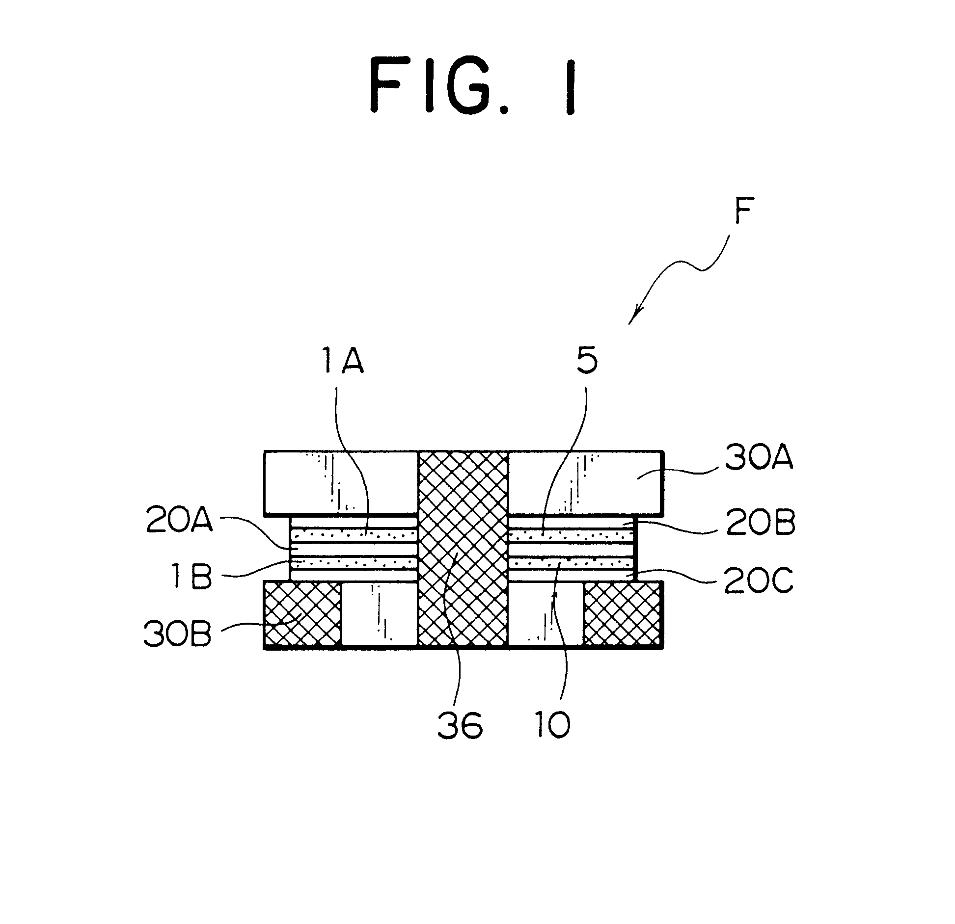
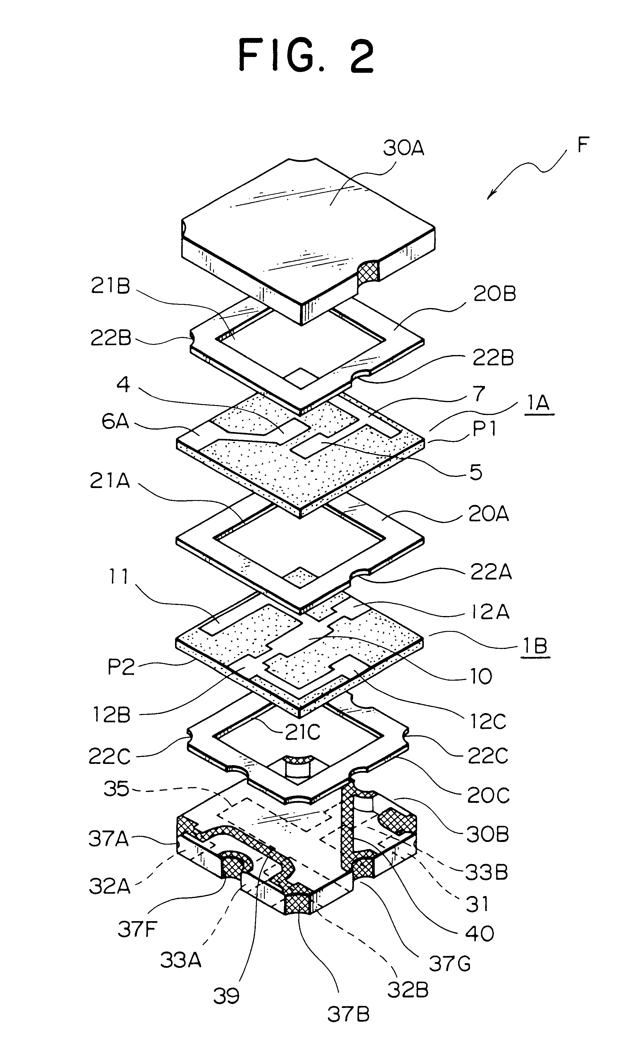
Referring to FIGS. 1 and 2, there is illustrated an arrangement of first embodiment of energy trapping type piezoelectric filter F according to one embodiment of the present invention.

The piezoelectric filter F comprises a first piezoelectric substrate 1A and a second piezoelectric substrate 1B having an identical configuration and arranged in layers with an adhesive sheet or spacer 20A interposed therebetween and insulating top and bottom plates 30A, 30B arranged on and under the respective piezoelectric substrates with adhesive sheets or spacers 20B, 20C also interposed therebetween.

Now, the piezoelectric substrates 1A, 1B will be described in detail by referring to FIG. 3.

The piezoelectric substrates 1A, 1B are made of a piezoelectric ceramic material such as PbTiO.sub.3, PbZrO.sub.3 or PbTiO.sub.3 --PbZrO.sub.3 and each of them carries el...


PUM


Abstract

An energy trapping type piezoelectric filter comprising a first piezoelectric substrate (1A) and a second piezoelectric substrate (1B) having an identical configuration and arranged in layers with an adhesive sheet or spacer (20A) interposed therebetween and insulating top and base plates (30A, 30B) arranged on and under the respective piezoelectric substrates with adhesive sheets or spacers (20B, 20C) also interposed therebetween, wherein a shielding conductive member (40) is provided on an upper surface of the insulating base plate (30B) for preventing an electromagnetic coupling between an input electrode (31) and output electrodes (32A, 32B), the shielding conductive member (40) being connected to grounding electrodes (33A, 33B).

Description

1. Field of the InventionThe present invention relates to an energy trapping type piezoelectric filter comprising a substrate having a plurality of oscillating sections.2. Prior ArtVarious energy trapping type piezoelectric filters have been proposed. For example, Japanese Patent Application Laid-Open No. 7-263999 discloses one of such piezoelectric filters. The disclosed filter comprises a pair of oscillating sections laterally arranged and a capacitor electrode centrally arranged on a surface of a single piezoelectric substrate. Such a conventional arrangement, however, has disadvantages that the piezoelectric substrate inevitably is forced to have an oblong profile and the piezoelectric filter has to have a large surface area for carrying the components thereon. Additionally, such a piezoelectric filter is subjected to various restrictions in terms of the profile, the thickness and the regions assigned to the oscillating sections to significantly limit the variable capacitance ra...

Claims


Application Information

Patent Timeline
Patent Type & Authority Patents(United States)
IPC IPC(8): H03H9/56H03H9/00H03H9/02H03H9/05H03H9/10H03H9/54
CPCH03H9/0561H03H9/562H03H9/1035
Inventor SUGIYAMA, TAKESHIWAKITA, MANABU
Owner NGK SPARK PLUG CO LTD
Learn More