
Adjustable pulley for fluid-operated transmissions

Inactive Publication Date: 2002-03-26
LUK LAMELLEN & KUPPLUNGSBAU BETEILIGUNGS KG
View PDF6 Cites 23 Cited by
  • Summary
  • Abstract
  • Description
  • Claims
  • Application Information

AI Technical Summary

Benefits of technology

Another object of the invention is to provide a method of eliminating or reducing the influence of centrifugal force upon the circulating body or bodies of fluid in the hydraulic control system for an adjustable pulley.
An additional object of the invention is to provide a pulley which can be utilized with advantage as a superior substitute for heretofore known adjustable pulleys in continuously variable transmissions.
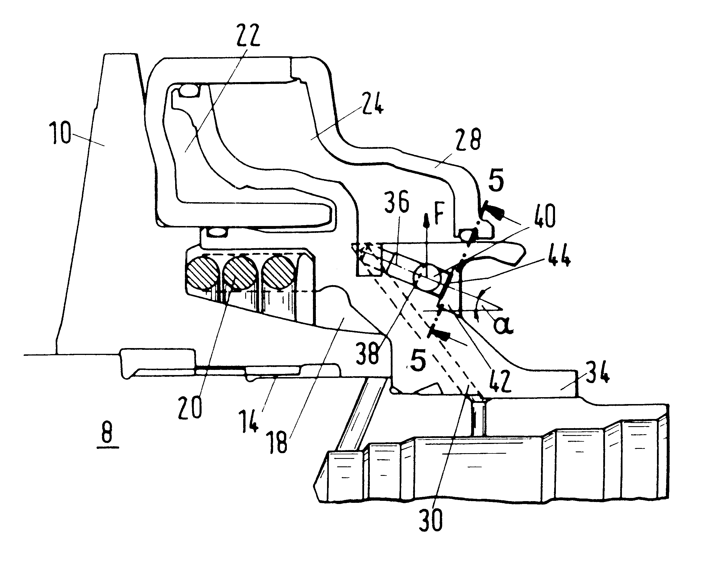
In accordance with a presently preferred embodiment, the valve comprises a valve body which shares rotary movements of the shaft about the second axis and has a channel which is inclined relative to the second axis and is provided with a seat, and a valving element which is movable in the channel against the seat under the action of centrifugal force which develops in response to rotation of the shaft about the second axis so that the force with which the valving element bears upon the seat to prevent the outflow of fluid from the additional chamber by way of the channel increases in response to increasing rotational speed of the shaft about the second axis.

Problems solved by technology

A drawback of presently known adjustable pulleys wherein the hydrulic adjusting or control system employs an additional plenum chamber and means for permitting gradual evacuation or expulsion of pressurized fluid from the additional chamber is that the fluid which is confined in the additional chamber opposes or prevents rapid shifting of the transmission between overdrive and underdrive or permits such shifting only if the hydraulic system which initiates and effects axial movements of the adjustable flange operates with a hydraulic fluid that is maintained at an extremely high pressure.

Method used


Image

  • Adjustable pulley for fluid-operated transmissions
  • Adjustable pulley for fluid-operated transmissions
  • Adjustable pulley for fluid-operated transmissions

Examples


Embodiment Construction

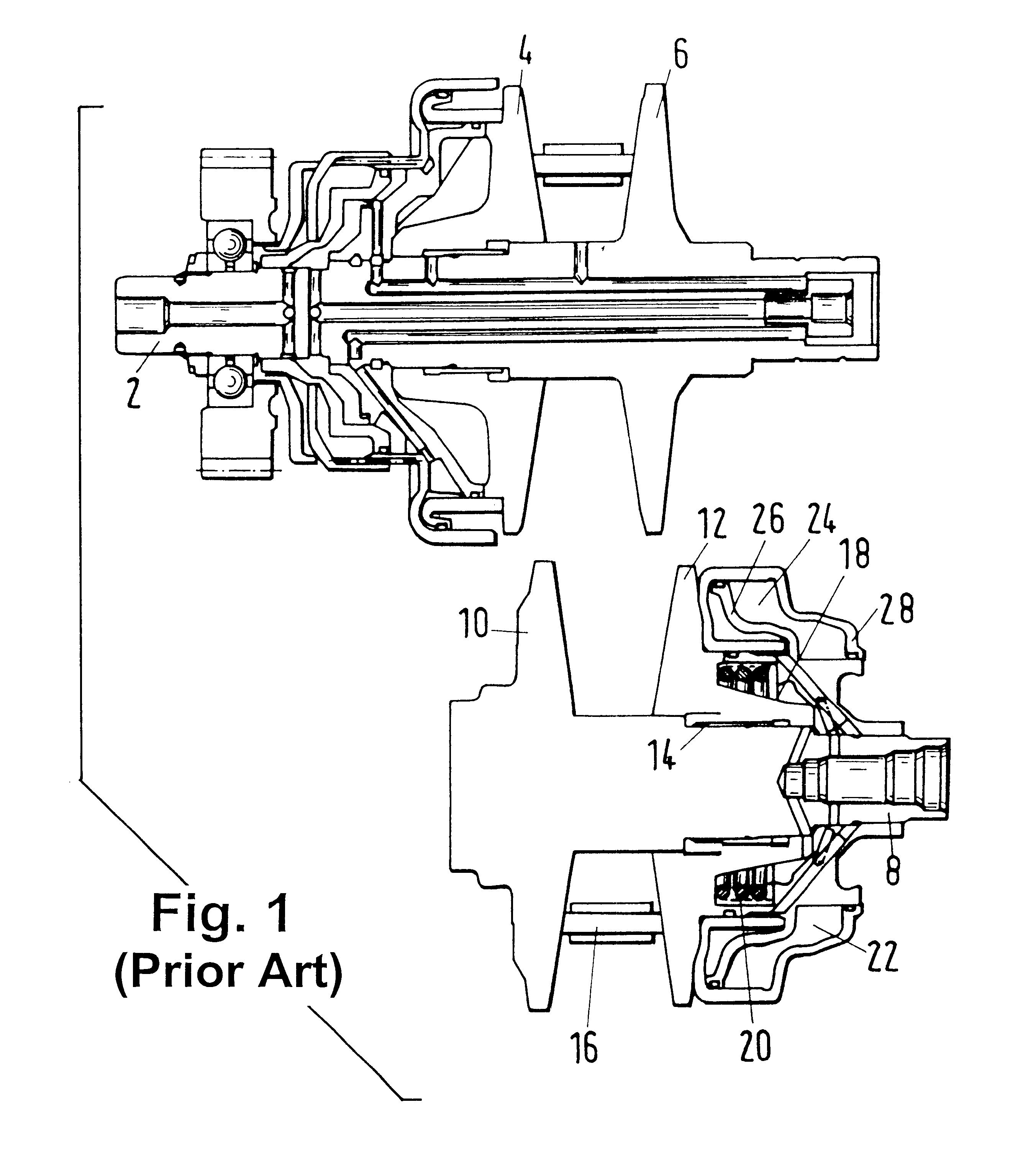
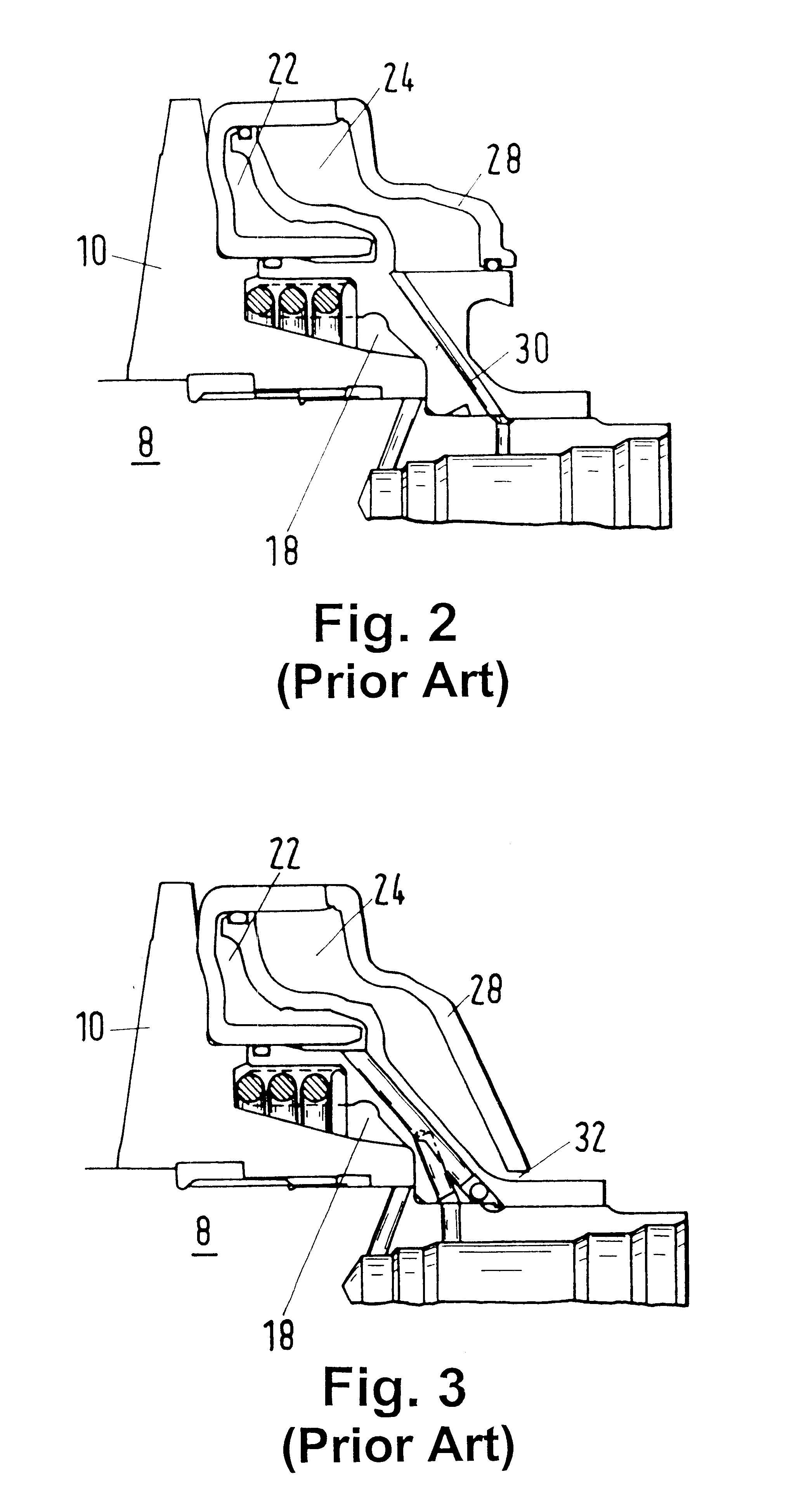
FIG. 1 shows a portion of a continuously variable transmission 1 (known as CVT) of the type disclosed in the aforementioned published German patent application Serial No. 195 44 644 A1. The transmission 1 comprises a first shaft 2 which can receive variable torque from the rotary output element of a prime mover (such as the combustion engine of a motor vehicle), e.g., by way of a clutch assembly and a torque sensor in a manner as disclosed, for example, in commonly owned U.S. Pat. No. 5,667,448 (granted Sep. 16, 1997 to Oswald Friedmann for "POWER TRAIN") or in commonly owned U.S. Pat. No. 5,711,730 (granted Jan. 27, 1998 to Oswald Friedmann and Armin Veil for "TORQUE MONITORING APPARATUS"). The disclosure of our German priority application Serial No. 199 24 224.0 (filed May 27, 1999), as well as the disclosures of all U.S. and foreign patents and patent applications identified in this specification, are incorporated herein by reference.

Referring again to FIG. 1, the shaft 2 carries...


PUM


Abstract

An adjustable pulley for use in a continuous variable transmission in the power train of a motor vehicle has an axially fixed first conical flange and an axially movable second conical flange. The hydraulic control system which moves the second flange relative to the first flange is provided with at least one first plenum chamber which receives pressurized fluid when the second flange is to move toward the first flange, and with an additional plenum chamber which receives pressurized fluid when the second flange is to move away from the first flange. The admission of pressurized fluid into the additional chamber is regulated in dependency upon the RPM of the flanges. Rapid evacuation of pressurized fluid from the additional chamber can take place by way of a relief valve which opens when the pressure of fluid in the additional chamber rises to a preselected value. This renders it possible to rapidly shift between overdrive and underdrive.

Description

The invention relates to improvements in continuously variable transmissions, e.g., so-called CVT transmissions which are frequently employed in the power trains of motor vehicles, and more particularly to improvements in adjustable pulleys or sheaves which are utilized in such transmissions.Transmissions of the above outlined character comprise adjustable pulleys wherein a first flange is movable axially toward and away from a fixed second flange by a hydraulic control system which employs one or more plenum chambers and a system of valves serving to regulate the flow of oil or another hydraulic fluid into and from the chamber(s). It is also known to counteract the adverse influence of centrifugal force upon the circulating body or bodies of hydraulic fluid in the plenum chamber(s) by resorting to an additional or extra plenum chamber and by providing a path for controlled gradual outflow of fluid from the additional chamber. Reference may be had, for example, to published German p...

Claims


Application Information

Patent Timeline
IPC IPC(8): F16H55/56F16H55/32F16H61/66F16H61/662F16H9/18
CPCF16H55/56F16H61/66272Y10T477/6197Y10T477/619Y10T477/6223Y10T477/624
Inventor FRIEDMANN, OSWALDWALTER, BERNHARD
Owner LUK LAMELLEN & KUPPLUNGSBAU BETEILIGUNGS KG
Learn More