
Physical channel assignment method and transmitter

a physical channel and assignment method technology, applied in multiplex communication, wireless commuication services, phase-modulated carrier systems, etc., can solve the inconvenience of always assigning the same logical channel to the adjacent frequency channel, fixed interference with adjacent channel, and communication cannot be performed through logical channel #1. , to achieve the effect of simple configuration

Inactive Publication Date: 2002-03-26
SONY CORP
View PDF10 Cites 14 Cited by
  • Summary
  • Abstract
  • Description
  • Claims
  • Application Information

AI Technical Summary

Benefits of technology

As described above, the values of the first pseudo-noise codes are used as the channel numbers of the physical channels and the physical channels are respectively assigned to the first logical channel; second pseudo-noise codes whose phases are shifted from those of the first pseudo-noise codes are obtained and the values of the second pseudo-noise codes are used as the channel numbers of the physical channels and the physical channels are respectively assigned to the second logical channel. Thus, the first and second logical channels can be prevented from being always located at the adjacent positions to each other on a frequency axis. Since the first and second logical channels can be prevented from being always adjacent to each other, the same adjacent channel interference can be prevented from being always supplied from the same logical channel, and the adjacent channel interference can be averaged.
As described above, the channel assignment table on which an interference with adjacent channels is uniformly distributed is previously prepared and values looked up from the channel assignment table are used as the channel numbers of the physical channels and the physical channels are assigned respectively to the plurality of logical channels. Thus, the same logical channels can be prevented from being always located at the adjacent positions to each other on a frequency axis with a relatively simple configuration, so that the adjacent channel interference can be averaged.

Problems solved by technology

In the above mentioned conventional channel assignment, however, although the different frequency channels f0 to f7 are respectively assigned to the logical channels #0 to #7 at the same time, there exists an inconvenience that the same logical channels are always assigned to the adjacent frequency channels.
As a result, there arises a problem that an interference with adjacent channels is always fixed.
As mentioned above, when the interference with adjacent channels is fixed, this causes a serious problem particularly when transmitted power is controlled.
As a result, there arises a risk that a communication cannot be performed through the logical channel #1 because a signal component sent originally from the logical channel #1 is buried in the adjacent channel interference waves.
Consequently, in the worst case, an inconvenience may occur that it is impossible to perform a communication.

Method used


Image

  • Physical channel assignment method and transmitter
  • Physical channel assignment method and transmitter
  • Physical channel assignment method and transmitter

Examples


first embodiment

(1) First Embodiment

(1-1) Entire Configuration of Cellular Radiocommunication System

Referring to FIG. 6, reference numeral 1 generally designates a cellular radiocommunication system to which the present invention is applied. The cellular radiocommunication system serves to perform a communication by connecting a base station 2 to a communication terminal unit 3 through a radio line. In this case, the base station 2 includes a transmitter 4, a channel control part 5 and a receiver 6. Further, the communication terminal unit 3 also includes a receiver 7, a channel control part 8 and a transmitter 9. The base station 2 and the communication terminal unit 3 perform a communication therebetween using these circuit blocks.

The transmitter 4 of the base station 2 gives a prescribed modulation process to data to be transmitted. The transmitter transmits a transmitting signal obtained as a result through frequency channels instructed by channel information sent from the channel control part ...

second embodiment

(2) Second Embodiment

In the above first embodiment, although an explanation is directed to an example in which one of the logical channels #1 to #7 generated is fixedly assigned to the communication with an arbitrary communication terminal unit 3, logical channels #1 to #7 which are assigned to a communication with a communication terminal unit 3 are further changed sequentially in terms of time according to a second embodiment, hence frequency channels used for the communication are further randomized.

For this purpose, according to the second embodiment, the logical channels #1 to #7 generated in the above described first embodiment are specified as logical subchannels and the logical subchannels #1 to #7 are combined together in terms of time so that logical channels ##1 to ##7 are formed. Then, one of the logical channels ##1 to ##7 is assigned to a communication with an arbitrary communication terminal unit 3.

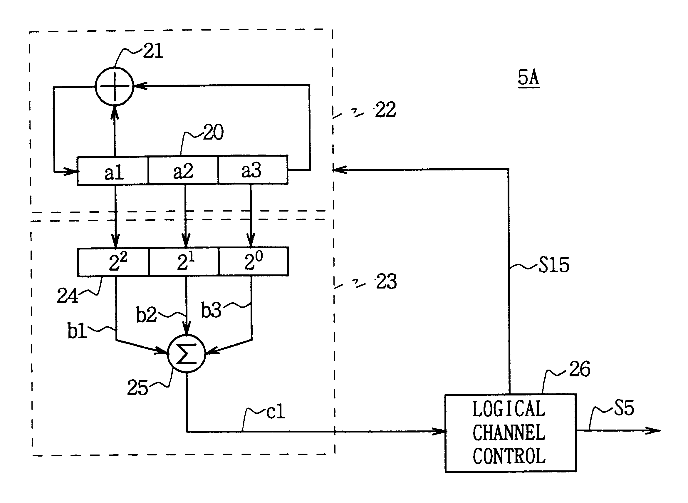
The configuration of a channel control part for realizing the above de...

third embodiment

(3) Third Embodiment

In the above first and second embodiments, while an explanation is given to the examples in which the channel assignment is carried out by using the M series codes generated by the M series code generator, according to a third embodiment, channel assignment tables in which the adjacent channel interference is equally distributed are previously provided and values looked up from the channel assignment tables are used to perform a channel assignment.

According to the third embodiment, logical channels are initially hierarchically represented by first and second logical subchannels and actual frequency channels are also hierarchically represented by first and second physical subchannels. For example, it is assumed that there exist 16 frequency channels f1 to f16 and 16 logical channels #1 to #16 are formed with the frequency channels f1 to f16 based on a frequency hopping scheme.

In this case, the logical channels #1 to #16 are noted by a hierarchical representation o...


PUM


Abstract

A physical channel assignment method prevents the same logical channels from being always adjacent to each other on a frequency axis so that any interference between the adjacent channels can be averaged. By using the values of first pseudo-noise codes as the channel numbers and assigning the physical channels (f1 to f7) to the first logical channel (#1); obtaining second pseudo-noise codes whose phases are shifted from those of the first pseudo-noise codes; and using the values of the second pseudo-noise codes as the channel numbers and assigning the physical channels (f1 to f7) to the second logical channel(#2), the first and second logical channels (#1, #2) can be prevented from being always adjacent to each other on the frequency axis.

Description

1. Field of the InventionThe present invention relates to a physical channel assignment method and a transmitter, and more particularly, is preferably applicable to a cellular radiocommunication system such as a portable telephone system.2. Description of the Related ArtIn the cellular radiocommunication system, an area for providing a communication service has been divided into cells with desired size. A base station has been provided as a fixed station in each of the cells and a communication terminal unit as a mobile station has been designed to perform a radiocommunication with the base station whose communication state seems to be most desirable.There have been proposed various types of systems as a communication system between the communication terminal unit and the base station. A representative communication system is called a frequency hopping scheme. With this frequency hopping scheme, assuming that, for instance, eight frequency channels f0 to f7 are prepared for communic...

Claims


Application Information

Patent Timeline
IPC IPC(8): H04B1/69H04B1/713H04Q7/36H04B1/715H04B7/24H04J13/16H04W16/02H04W16/12
CPCH04B1/7143H04L27/20H04W16/02H04W16/12H04B2001/7154H04W72/082H04W28/04H04W72/00H04W72/0453H04W72/541
Inventor SAKODA, KAZUYUKISUZUKI, MITSUHIRO
Owner SONY CORP
Learn More