Method and apparatus for electronic power control

a technology of electronic power control and electronic power supply, applied in the direction of power conversion systems, ac-ac conversion, instruments, etc., can solve the problems of increased power consumption, increased power consumption, and use of elaborate and expensive array of optional harmonics

Inactive Publication Date: 2002-04-02
MICROPLANET
View PDF6 Cites 69 Cited by
  • Summary
  • Abstract
  • Description
  • Claims
  • Application Information

AI Technical Summary

Problems solved by technology

The occurrence of this problem is well known Most manufacturers of conventional PFC systems use an elaborate and expensive array of optional harmonic "traps" that have to be customized to a specific installation.
In most respects the waveform is identical to the previous printout, but the passive damper clearly contributes to greater power consumption as the input current increases to 4.5ARMS, without significant improvement in the waveform over active damping alone.
Secondly, the tests were not conducted in a worst case resonance scenario; in an industrial plant with far less "clean" power, multiple motor and PFC resonant combinations typically create fuse blowing and PFC capacitor failures, and have much greater need for the kind of PFC demonstrated here.

Method used


Image

  • Method and apparatus for electronic power control
  • Method and apparatus for electronic power control
  • Method and apparatus for electronic power control

Examples


Embodiment Construction

Turning now to the drawings, the invention will be described in a preferred embodiment by reference to the numerals of the drawing figures wherein like numbers indicate like parts.

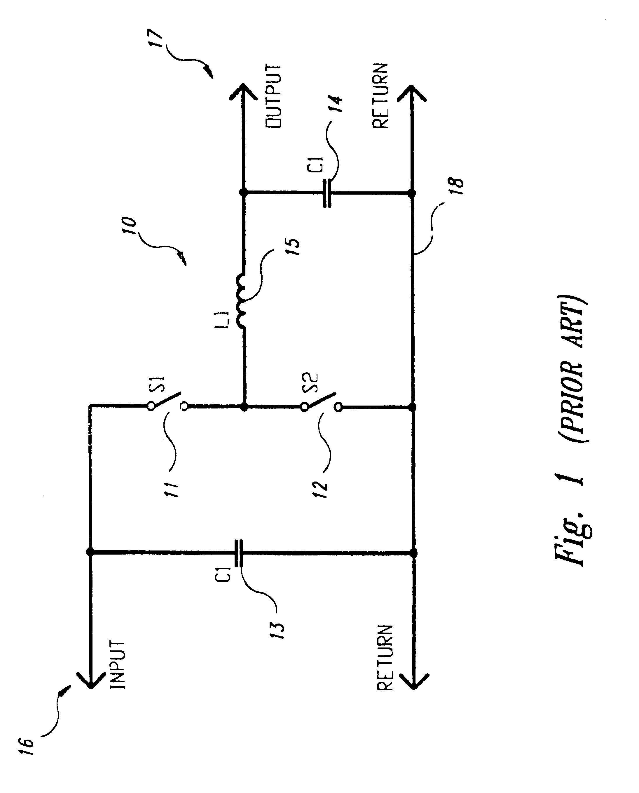
FIG. 1 is a conventional configuration of known buck regulator topology, included here as a point of reference. Convention buck regulator 10 has a first switch 11, a second switch 12, input filter capacitor 13, output filter capacitor 14, inductor 15, input 16, output 17, and return 18. Switches 11 and 12 alternately close and open (are modulated), so that in conjunction with inductor 15, in well known fashion, voltage at output 17 may be stepped down from the voltage at input 16 in proportion to the duty cycle modulation of the switches.

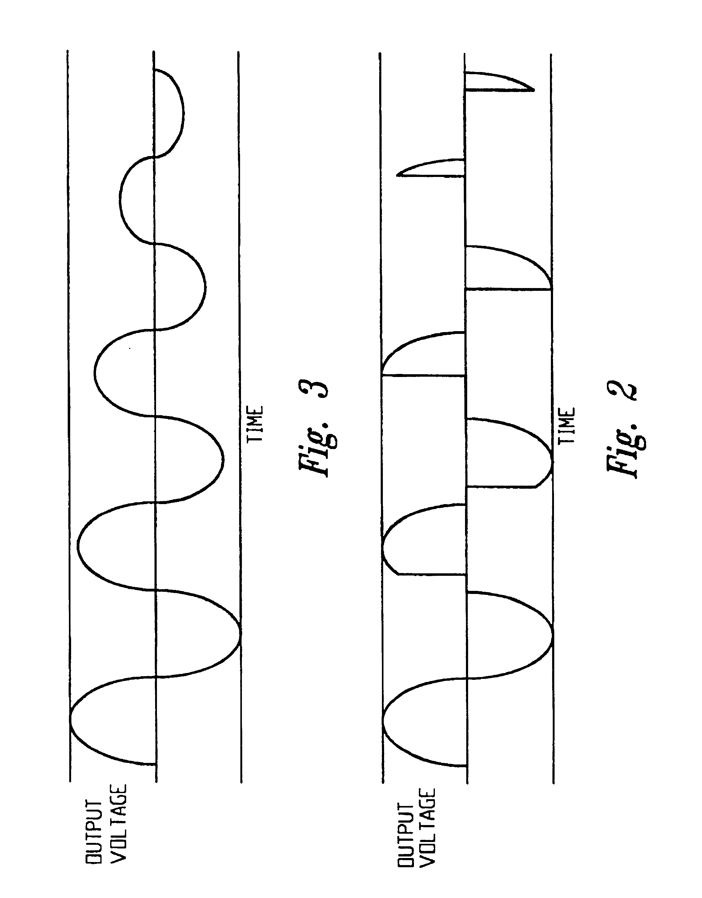
FIG. 2 is a graphic representation of the broken waveform output from a phase angle fired triac, to be compared with FIG. 3 which is a graphic representation of an output voltage waveform having its amplitude varied over time by the power controller of the invention, witho...


PUM


Abstract

The method of the invention in one aspect involves electronic power control by varying the amplitude of an electrical power supply voltage, independent of frequency, whereby the output frequency will always be the same as the input frequency. An electrical circuit apparatus for accomplishing this function in a preferred embodiment is also disclosed herein. The preferred circuitry of this aspect of the invention uses four solid state switches, such as IGBT's, four diodes, an inductor, input and output filters and novel controlling circuitry. The controller apparatus and methods of the invention may be used to implement all otherwise conventional converter types, buck, boost, and inverting (and duals of these) versions to obtain different regulating characteristics, including galvanic isolation of the output from the input. The inventive methods and devices may be used in power factor correction, voltage and / or current harmonic filtering and neutralization, line and load conditioning, control of power transfer between two power grids, and programmable control of surges, sags, dropouts and most other voltage regulation problems.

Description

The invention relates to the field of electrical power conversion and control, across a wide range of current and voltages; more particularly, it relates to method and apparatus for electronically implemented power control, more particularly, those implemented with switch mode power conversion techniques.An electrical power conversion circuit is a circuit in which electrical power is changed so that a power source with a voltage or current can serve a load requiring a different voltage or current. In switch mode conversion circuits and power conversion techniques, power is typically changed from a supply that is higher in current or voltage to serve a load requiring lower current or voltage, or from a supply that is lower in voltage or current to a load requiring higher voltage or current. Where high conversion efficiency is made possible by design of the circuit, power output is substantially equal to power input. Where voltage--ampere products (VA) are close to the same at both ou...

Claims


Application Information

Patent Timeline
Patent Type & Authority Patents(United States)
IPC IPC(8): H02M5/02H02M5/293
CPCH02M5/293
Inventor BARETICH, DAVID F.WIEGAND, GREGORY P.
Owner MICROPLANET
Why Eureka
Try Eureka