Component holder for a hall sensor and process for manufacturing a component holder

a technology for components and sensors, applied in the direction of instruments, casings/cabinets/drawers, pulse techniques, etc., can solve the problems of high cost of mounting hall sensors and component holders on printed circuit boards, inability to play-free seating of hall sensors, and difficulty in determining the rotational position of a rotor to be detected that belongs to an adjusting motor with a high degree of precision

Inactive Publication Date: 2002-04-02
ROBERT BOSCH GMBH
View PDF9 Cites 15 Cited by
  • Summary
  • Abstract
  • Description
  • Claims
  • Application Information

AI Technical Summary

Problems solved by technology

However, this type of mounting of the Hall sensor and component holder on the printed circuit board is costly.
In addition, the superposition of the component holder does not permit a play-free seating of the Hall sensor in the component holder.
Without a play-free seating, though, it is very diff

Method used


Image

  • Component holder for a hall sensor and process for manufacturing a component holder
  • Component holder for a hall sensor and process for manufacturing a component holder
  • Component holder for a hall sensor and process for manufacturing a component holder

Examples


Embodiment Construction

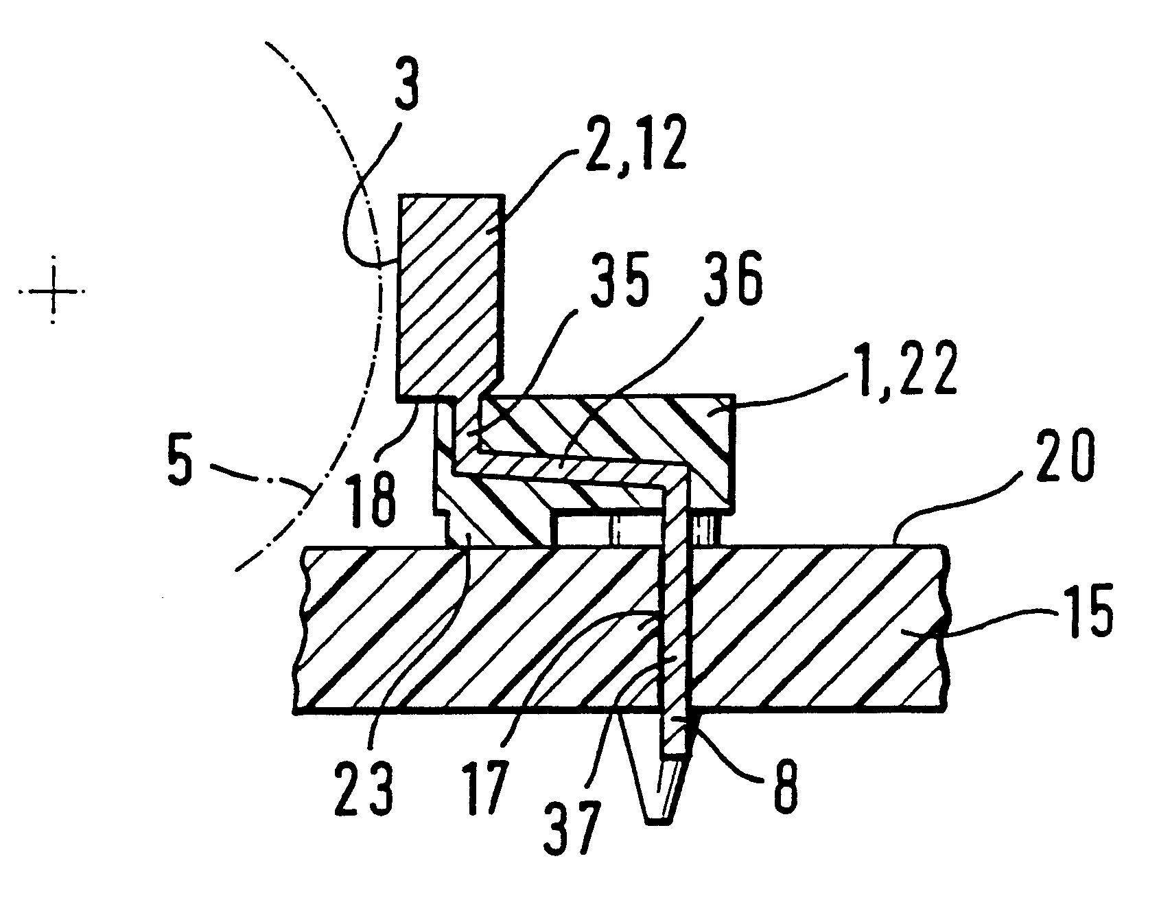
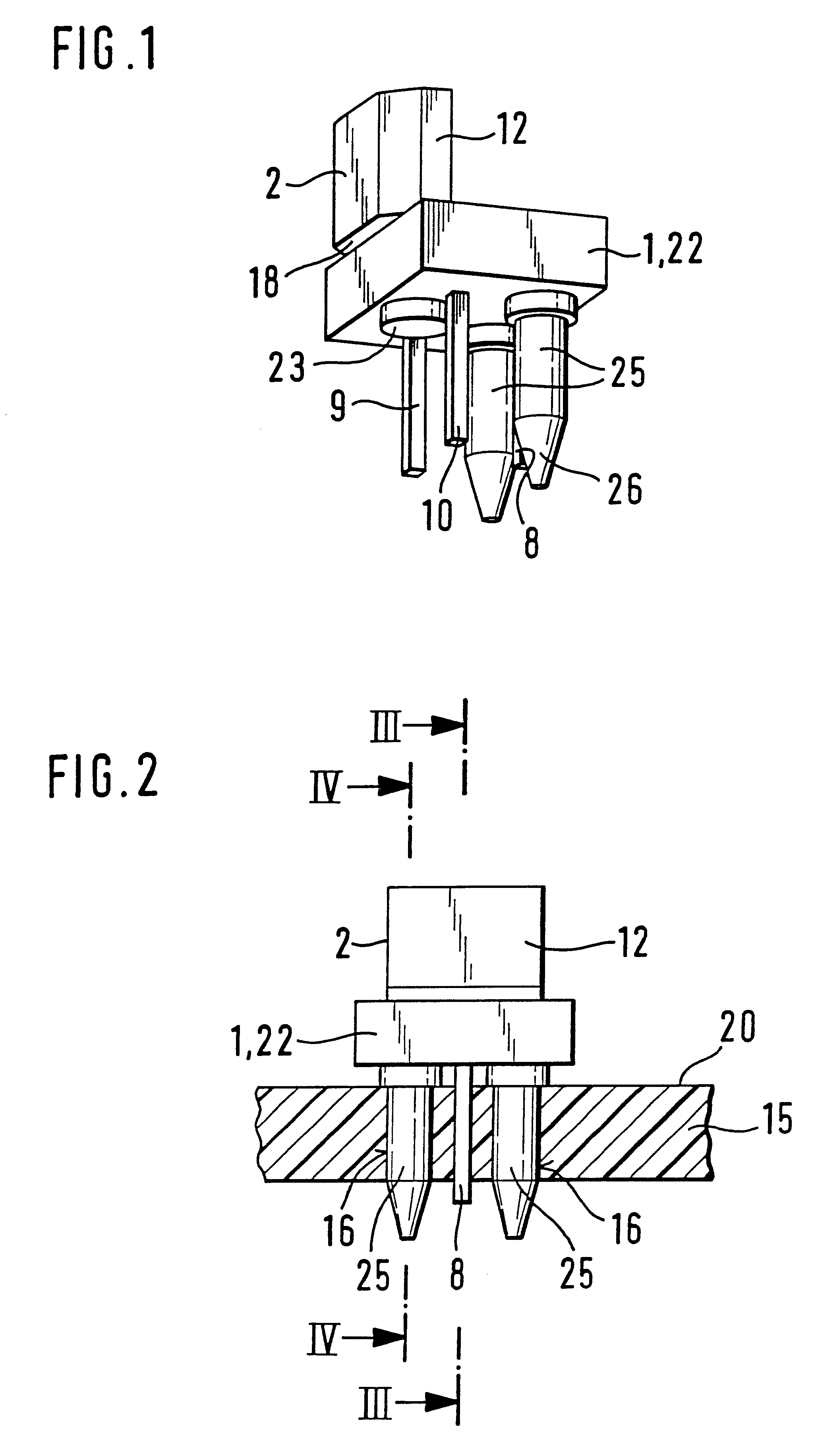
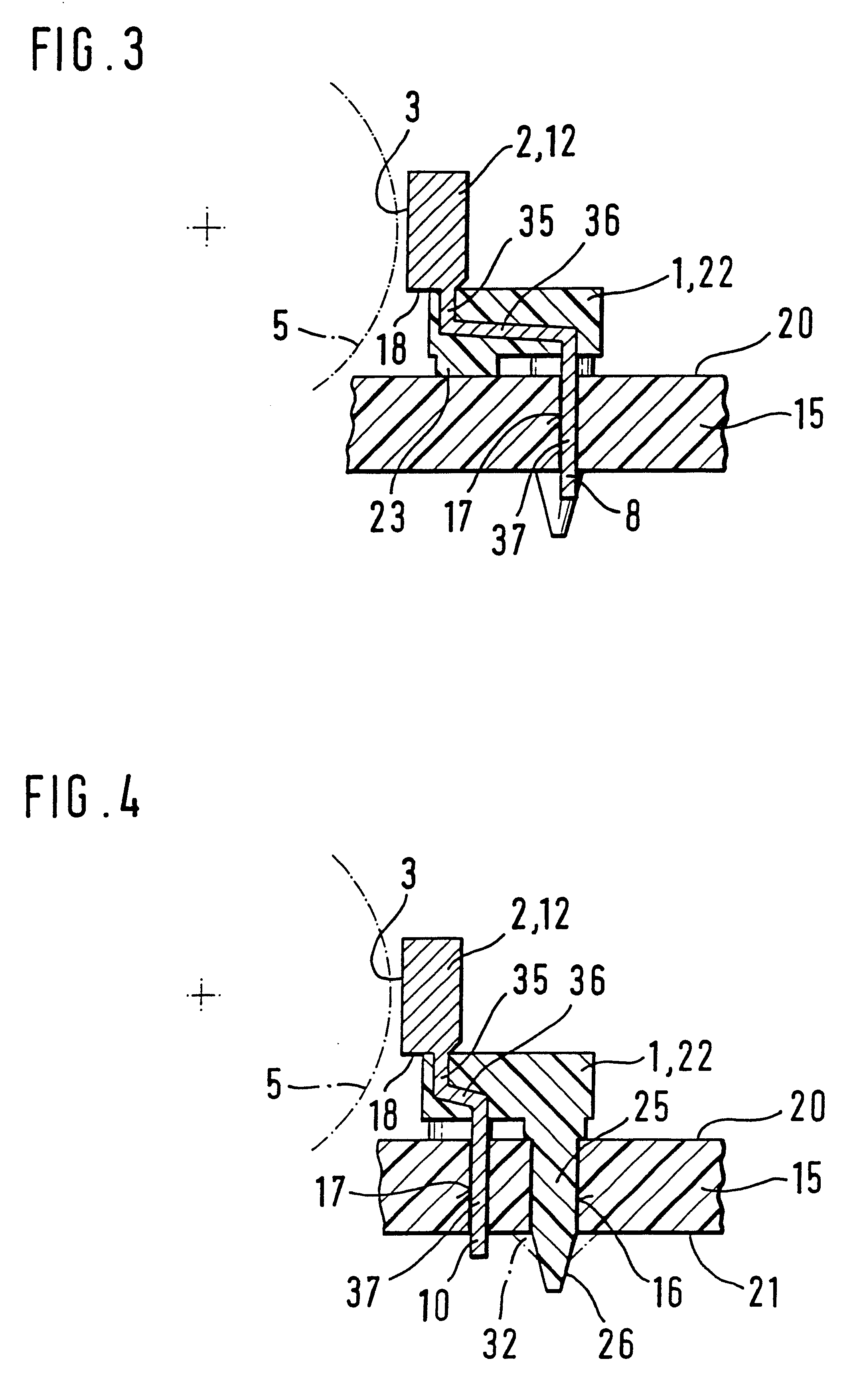
FIG. 1 is a perspective representation of a component holder 1 with a Hall sensor 2 according to a first exemplary embodiment according to the invention. For example, the Hall sensor 2 is used in a known manner for position detection of the rotational position of a rotor 5 that is indicated with dashed lines in FIGS. 3, 4, and 9. The rotor 5 is a component of an adjusting motor, not shown in detail, of the kind that is used, for example, for window regulator motors or as a sunroof drive mechanism for motor vehicles. Distributed on its circumference, the rotor 5 has magnet rings, not shown in detail, which preferably have multi-poled, permanently magnetized regions. The rotational position of the rotor 5 can be determined in a known manner in the cooperation of the magnetized regions of the rotor 5 with the Hall sensor.2.

Hall sensors 2 of this kind have an essentially block-shaped housing 12. As shown in FIG. 5, a bottom view of the component holder 1 with Hall sensor 2, the Hall sen...


PUM


Abstract

Known Hall sensors are fastened to a printed circuit board by way of component holders in order to achieve an exact positioning and securing on a printed circuit board in relation to a magnet ring of a rotor of an adjusting motor. A component holder for a Hall sensor is partially injection molded only onto connecting prongs of the Hall sensor or is injection molded onto connecting prongs and at least partially onto a housing of the Hall sensor. The component holder for a Hall sensor according to the invention is provided for adjusting motors, such as window regulator motors of motor vehicles.

Description

PRIOR ARTThe invention is based on a component holder for a Hall sensor and on a process for manufacturing a component holder A component holder for a Hall sensor is already known (German Patent Disclosure 32 35 204), which is placed over the Hall sensor in order to hold it in all directions so that it is possible to position the Hall sensor on a printed circuit board in a narrow radial tolerance range in relation to a circumferential magnet ring. The component holder has injection molded centering pins which can be inserted into corresponding openings of the printed circuit board. In order to mount the Hall sensor, its connecting prongs are first slid into openings of the printed circuit board and then the component holder is placed over the Hall sensor until the component holder, with its underside, comes into contact with the surface of the printed circuit board. However, this type of mounting of the Hall sensor and component holder on the printed circuit board is costly. In addi...

Claims


Application Information

Patent Timeline
IPC IPC(8): G01D11/24H02K11/00H05K3/30B29C45/14H01L43/04H02K11/215H02K29/08
CPCG01D11/245H05K3/301H02K11/0021H02K11/215
Inventor RIEHL, GUENTHERHAGER, MARTIN
Owner ROBERT BOSCH GMBH
Why Eureka
Try Eureka