Method for the terrestrially transmitting digital signals

a digital signal and terrestrial transmission technology, applied in the field of terrestrial transmission digital signals, can solve the problems of not all of the terrestrially possible tv channels can be occupied, the selectivity and linearity of the receiver input stage cannot be guaranteed, and the receiver input stage cannot be selected and linear

Inactive Publication Date: 2002-04-02
NOLA SEMICON
View PDF21 Cites 79 Cited by
  • Summary
  • Abstract
  • Description
  • Claims
  • Application Information

AI Technical Summary

Problems solved by technology

The selectivity and linearity of the receiver input stage are at best always limited, and as a result, when all the theoretically possible TV channels and especially neighboring TV channels are occupied with analog-modulated TV programs, problems can occur because of excessive differences between the levels of the channel in use and the neighboring channel and because of cross modulation and intermodulation.
Because of the area coverage and resultant overlaps among various stations for a certain region, the result of this is that by far not all of the terrestrially possible TV channels can be occupied.
The resultant scarcity of frequencies is made even worse by the fact that for two stations that are broadcasting the same program, different frequencies have to be provided in the overlapping region, because otherwise common channel interference such as ghost images as a rule occur, because of differences in transit time and extinction zones from interference.

Method used


Image

  • Method for the terrestrially transmitting digital signals
  • Method for the terrestrially transmitting digital signals
  • Method for the terrestrially transmitting digital signals

Examples


Embodiment Construction

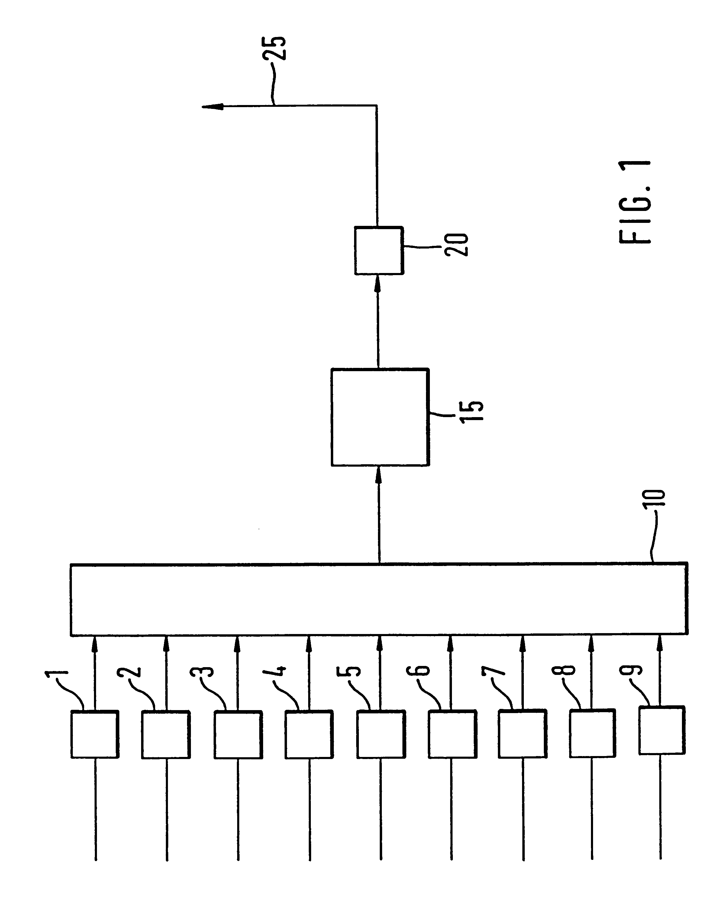
In FIG. 1, reference numeral 10 indicates a multiplexer, to which one digital TV broadcasting signal each is supplied via a first, second and third encoder 1, 2, and 3, and to which one digital radio signal each is supplied via a fourth through ninth encoder 4-9. The multiplexer 10 is connected via modulator 15 and an amplifier 20 to a transmitting antenna for terrestrial broadcasting of the digital radio and TV broadcasting signals.

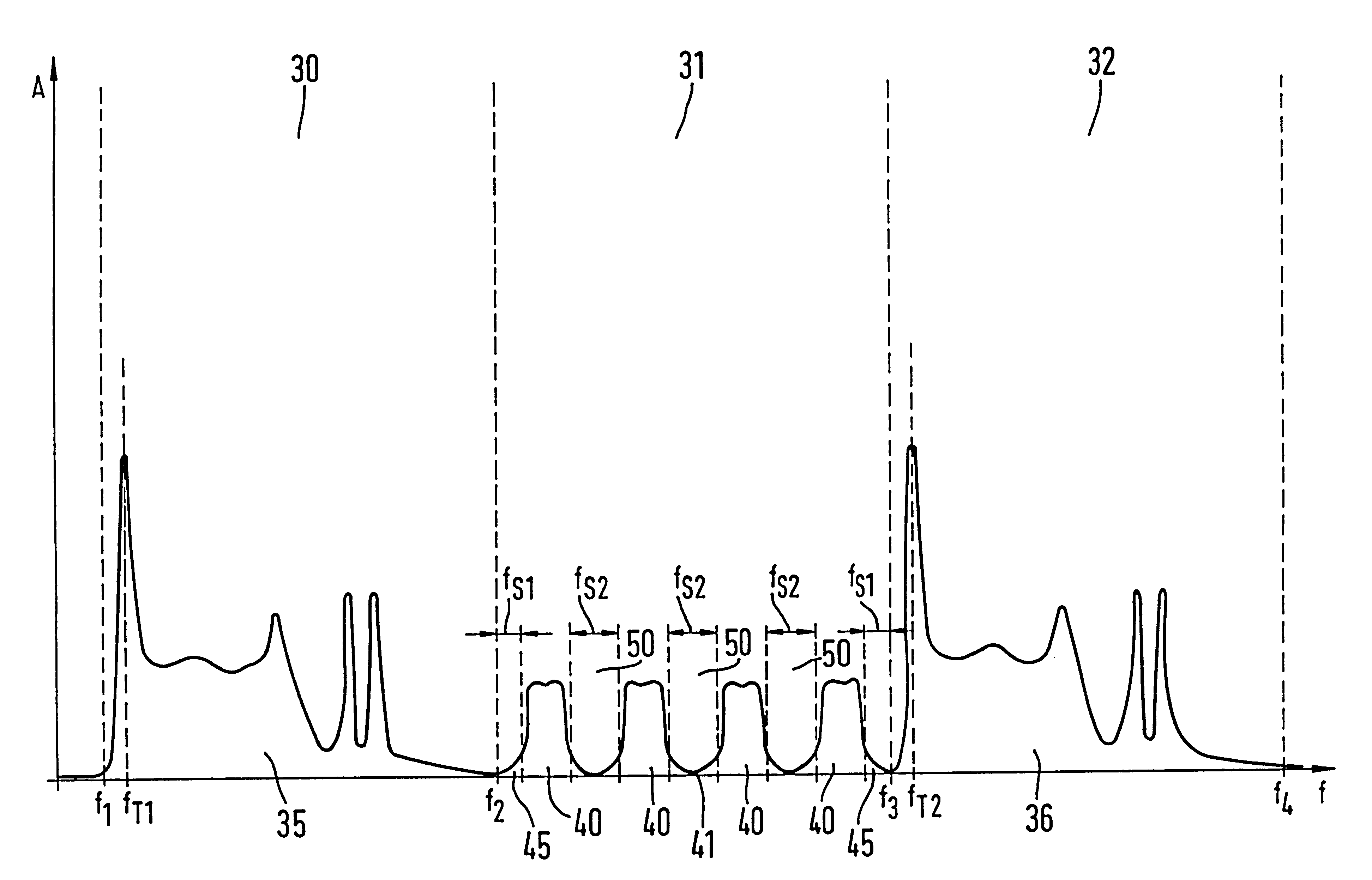
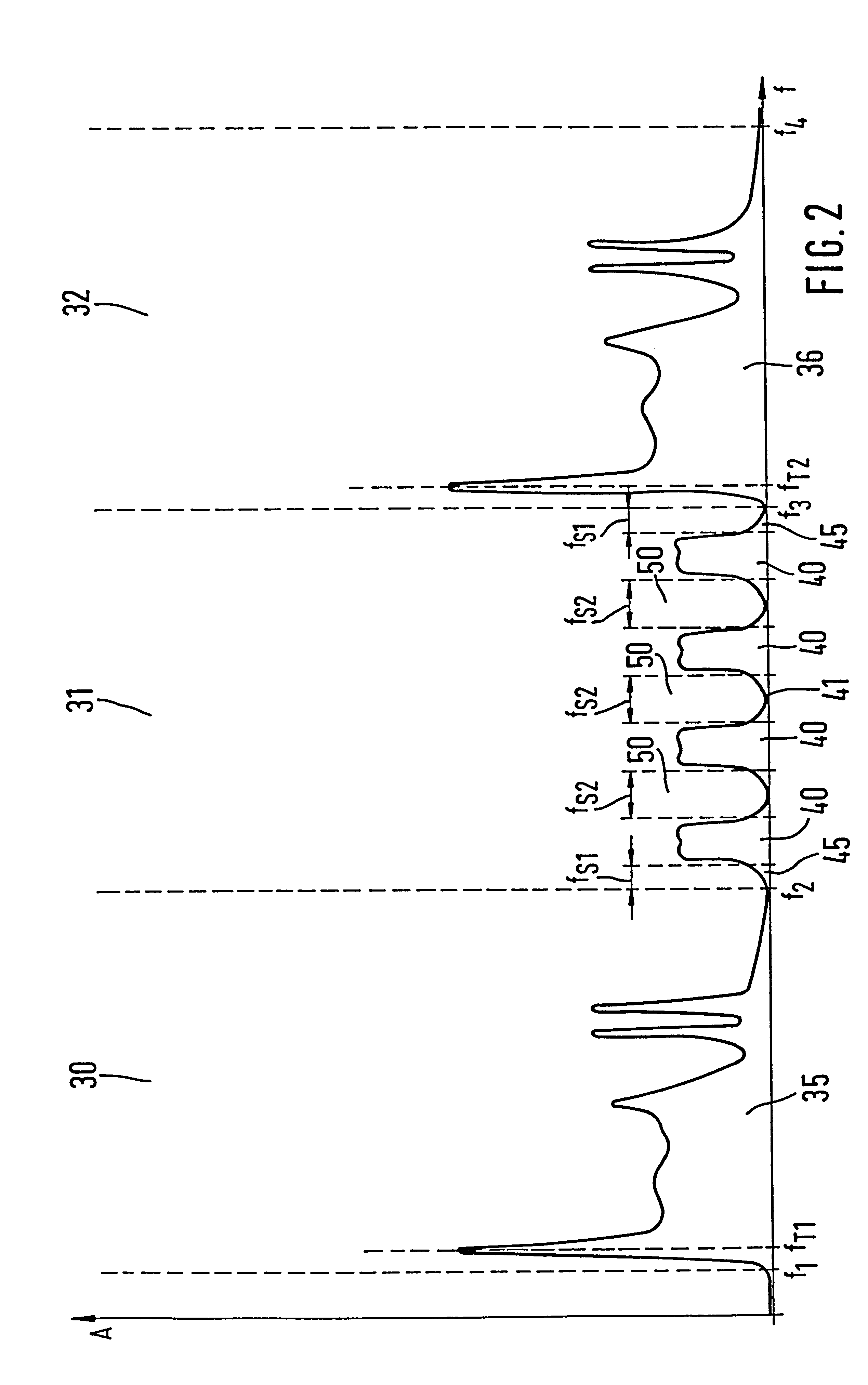
The encoders 1-9 reduce the data quantity of the digital TV broadcasting signals and digital radio signals, thus limiting the frequency spectra of the digital signals. For reducing the data quantity, data compression algorithms are suitable, such as MPEG 1, MPEG 2, or MPEG 4 (MPEG=motion picture expert group). For audio data reduction, the ISO MPEG 11172 standard, with its various layers, is suitable. The digital signals supplied to the multiplexer 10 via the encoders 1-9 are combined in the multiplexer 10 by frequency multiplexing into a digital signal ...


PUM


Abstract

A method is proposed that is used for terrestrial transmission of at least one digital signal, in particular a digital radio and/or TV broadcasting signal. In this method, the at least one digital signal, reduced in its data quantity by coding, is modulated, preferably by the OFDM method, and converted into the frequency position of at least one channel, adjacent to at least one occupied or unoccupied channel (30, 32) for transmitting an analog TV broadcasting signal, and is broadcast in this frequency position. The dynamic scope and the amplitude of the spectrum (41) of the at least one digital signal must undershoot a respectively predetermined value that is markedly less than the dynamic scope or amplitude of the video carrier of the spectrum (35, 36) of the analog TV broadcasting signal, so that there will be only slight intermodulation and cross modulation with other digital signals or with analog signals of other channels. The spectrum (41) of the at least one digital signal is transmitted, separated from at least one adjacent channel (30, 31) by a protective frequency margin (45). When a plurality of digital signals are transmitted in the at least one channel (31), the frequency ranges of at least two digital signals are transmitted, separated from one another by a protective frequency margin (50).

Description

PRIOR ARTThe invention is based on a method as generically defined by the main claim.In terrestrial signal distribution of television signals, both topographic features and above all varying distances of the receiver from the various stations can create very great differences in field intensity at the reception site. The selectivity and linearity of the receiver input stage are at best always limited, and as a result, when all the theoretically possible TV channels and especially neighboring TV channels are occupied with analog-modulated TV programs, problems can occur because of excessive differences between the levels of the channel in use and the neighboring channel and because of cross modulation and intermodulation. The attempt is made to limit these problems by avoiding occupation of neighboring channels. The neighboring channels that are thus not usable are also called forbidden channels. Because of the area coverage and resultant overlaps among various stations for a certain...

Claims


Application Information

Patent Timeline
Patent Type & Authority Patents(United States)
IPC IPC(8): H04L5/02H04H1/00H04N7/08H04H20/42H04H20/72H04J1/00H04J11/00H04N7/00
CPCH04H20/42H04H20/72H04N7/0803H04L5/023H04H2201/20
Inventor SIEGLE, GERT
Owner NOLA SEMICON
Why Eureka
Try Eureka