Beam splitter assembly and interferometer having a beam splitter assembly

a splitter assembly and beam technology, applied in the direction of instruments, measurement devices, optics, etc., can solve the problems of affecting the quality of beam splitter assembly,

Inactive Publication Date: 2002-04-09
DR JOHANNES HEIDENHAIN GMBH
View PDF20 Cites 30 Cited by
  • Summary
  • Abstract
  • Description
  • Claims
  • Application Information

AI Technical Summary

Problems solved by technology

The principal disadvantage of a beam splitter of this kind is that it is relatively expensive to manufacture.
Any manufacturing-related pyramidal flaws in the Kosters prism cause the path to diverge from the ideal path to a greater or lesser degree.
In particular, problems occur if the path length between the beam splitter assembly and the downstream measuring reflector and reference reflector in the measuring arm and referenc

Method used


Image

  • Beam splitter assembly and interferometer having a beam splitter assembly
  • Beam splitter assembly and interferometer having a beam splitter assembly
  • Beam splitter assembly and interferometer having a beam splitter assembly

Examples


first embodiment

A schematic view of the interferometer according to the present invention in which the beam splitter assembly described above is used is shown in FIG. 3.

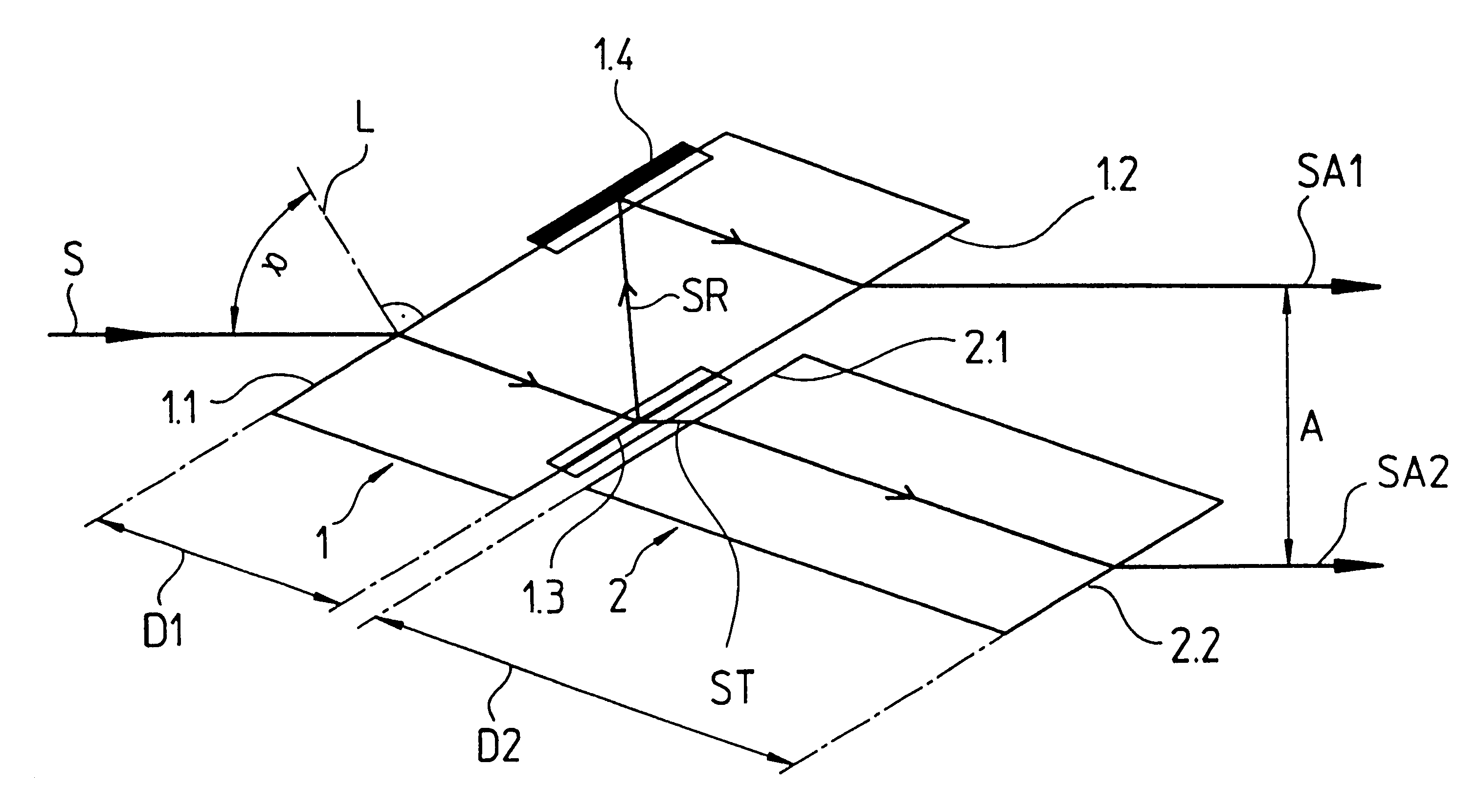
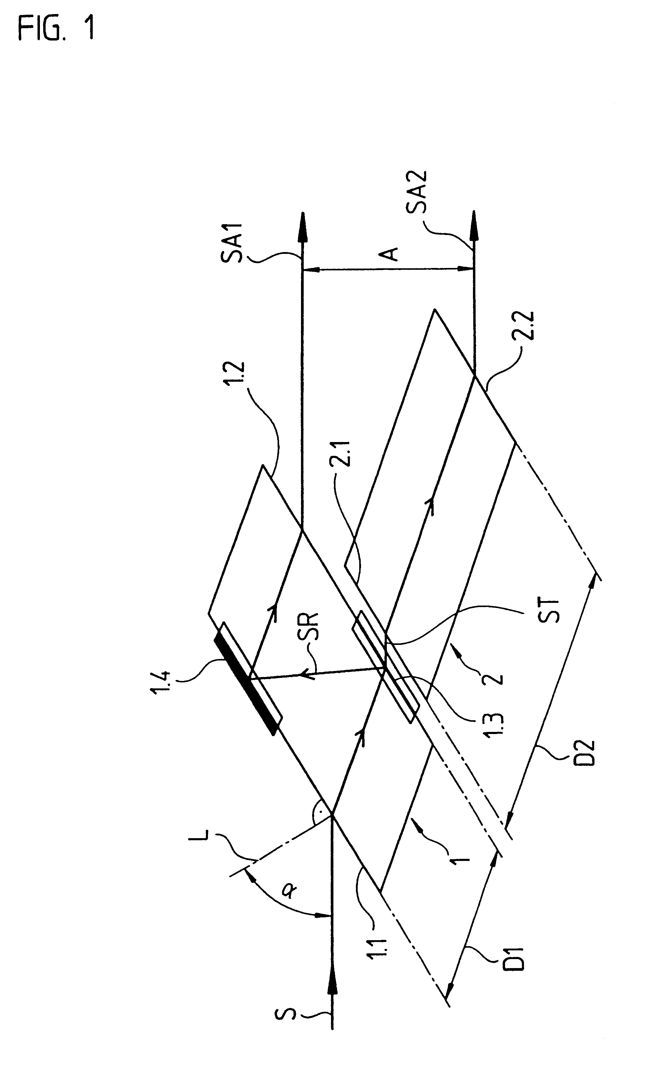
Interferometer 50 according to the present invention includes light source 51, such as an HeNe laser that is known, whose output beam enters beam splitter assembly 100 as incoming beam S. This assembly has the same design as the first exemplary embodiment described with the help of FIG. 1.

Two parallel outgoing beams SA1, SA2 exit beam splitter assembly 100. First outgoing beam SA1 travels into a reference arm of interferometer 50, in which stationary reference reflector 53 is arranged at a certain distance from beam splitter assembly 100. Reference reflector 53 is preferably a known triple prism.

The second outgoing beam travels into the measuring arm of interferometer 50, in which measuring reflector 54, whose relative position or absolute position is to be determined, is arranged movably in measuring direction x. Measuring reflecto...

second embodiment

interferometer 60 according to the present invention is shown in FIG. 6. In the case of this embodiment, it is possible to detect the linear movement of an object to be measured and, at the same time, to measure any rotational movement of a linearly movable assembly. Possible applications include semiconductor manufacturing systems such as wafer steppers.

The embodiment shown in FIG. 6 includes two measuring reflectors 54A, 54B which are designed as triple prisms and are arranged together in a modular unit 55. Modular unit 55 can be moved in the x direction relative to the rest of the interferometer components. Furthermore, modular unit 55 can be rotated about axis z, which is perpendicular to the drawing plane. Movements in the x direction as well as rotation about the z axis can be detected with the help of the second interferometer embodiment according to the present invention.

To detect rotation about the z axis, certain modifications relative to the examples described above must ...

third embodiment

the interferometer according to the present invention is described with the help of FIG. 7. In the two types of interferometer embodiments described above, triple prisms were used as reflectors. By contrast, in this case, a planar mirror is used as a reflector in at least one interferometer arm, for example in the measuring arm. This is particularly useful if movements in a plane are to be detected with the help of the interferometer according to the present invention, for example when simultaneous movements in the x and y directions are detected. In such instances, to allow position determination using the interferometer, spatially elongated reflectors must be used so that retro-reflection from each measuring reflector can occur even if there is simultaneous movement in the x and y directions. Retro-reflective elements such as triple prisms are not suitable for this purpose.

In this example, linear polarized incoming beam S supplied by a light source (not shown in FIG. 7) first reac...


PUM


Abstract

A beam splitter assembly and an interferometer using the beam splitter assembly are described. The beam splitter assembly splits an incoming beam of rays that impinges thereon into at least one first outgoing beam and at least one second outgoing beam parallel thereto. To accomplish this, the beam splitter assembly includes a beam splitter element and a compensating element. The beam splitter element includes a transparent plate having two parallel boundary surfaces. The compensating element is arranged with respect to the beam splitter element so that the two outgoing beams propagate parallel to one another, and have essentially traveled the same optical path lengths in the beam splitter element as in the compensating element.

Description

The present invention relates to a beam splitter assembly and to an interferometer using the beam splitter assembly.DESCRIPTION OF RELATED ARTInterferometers generally include one or a plurality of beam splitter assemblies used to physically split a beam of rays into a measuring path and a reference path, often referred to as the measuring arm and the reference arm. This assembly is generally used to combine the measuring path and the reference path in the opposite direction of the beam. The optical axes of the measuring arm and reference arm are oriented differently relative to one another, depending on the type of interferometer. Thus, the measuring arm and the reference arm may be essentially perpendicular to one another or parallel to one another.In the former case, beam-splitting prisms onto which a triple prism that creates the reference arm is cemented are generally used. This is shown, for example, in U.S. Pat. No. 4,802,765.In the latter case, where the measuring path and t...

Claims


Application Information

Patent Timeline
IPC IPC(8): G01B9/02G02B27/10G02B5/04
CPCG02B27/106G02B27/144G01B9/02058G01B9/02061G02B27/145G01B2290/70
Inventor SPANNER, ERWIN
Owner DR JOHANNES HEIDENHAIN GMBH
Why Eureka
Try Eureka