Manufacturing method of batteries

a manufacturing method and battery technology, applied in the direction of sustainable manufacturing/processing, cell components, flat cell grouping, etc., can solve the problems of reducing the gap space in the envelope film body 2, the inability to invite fluctuation in battery performance and quality, and the accuracy of electrolytic solution injection

Inactive Publication Date: 2002-04-16
TOSHIBA BATTERY
View PDF5 Cites 38 Cited by
  • Summary
  • Abstract
  • Description
  • Claims
  • Application Information

AI Technical Summary

Benefits of technology

According to the present invention, in the steps of manufacturing polymer batteries, a prescribed amount of electrolytic solution can be injected with ease and accuracy. Accordingly, batteries of high quality can be manufactured with high yield. That is, by utilizing part of the envelope film body as a reservoir of the injected electrolytic solution, after supplying the prescribed amount of electrolytic solution, even in the continuous manufacturing process, interruption and switching of operations are made unnecessary. Further, even if the region for injecting the electrolytic solution of such as the battery element is dense to invite a difficulty in impregnating the electrolytic solution, the impregnation at a reduced pressure can be implemented as it is. Accordingly, good productivity can be maintained and since the definite amount of injection of the electrolytic solution is possible, batteries of high quality can be provided.

Problems solved by technology

However, reducing the gap space in the envelope film body 2 as small as possible invites a difficulty when the prescribed electrolytic solution is injected.
As a result, there is a possibility that the prescribed amount of the electrolytic solution is not injected and is not held inside thereof, resulting in liability to invite fluctuation of battery performance and quality.
As a result, due to evaporation of the component of the injected electrolytic solution or to accumulated error of the amount of injection caused by separated injection of the electrolytic solution, accuracy of, the amount of injection of the electrolytic solution is lowered.

Method used


Image

  • Manufacturing method of batteries
  • Manufacturing method of batteries
  • Manufacturing method of batteries

Examples


Embodiment Construction

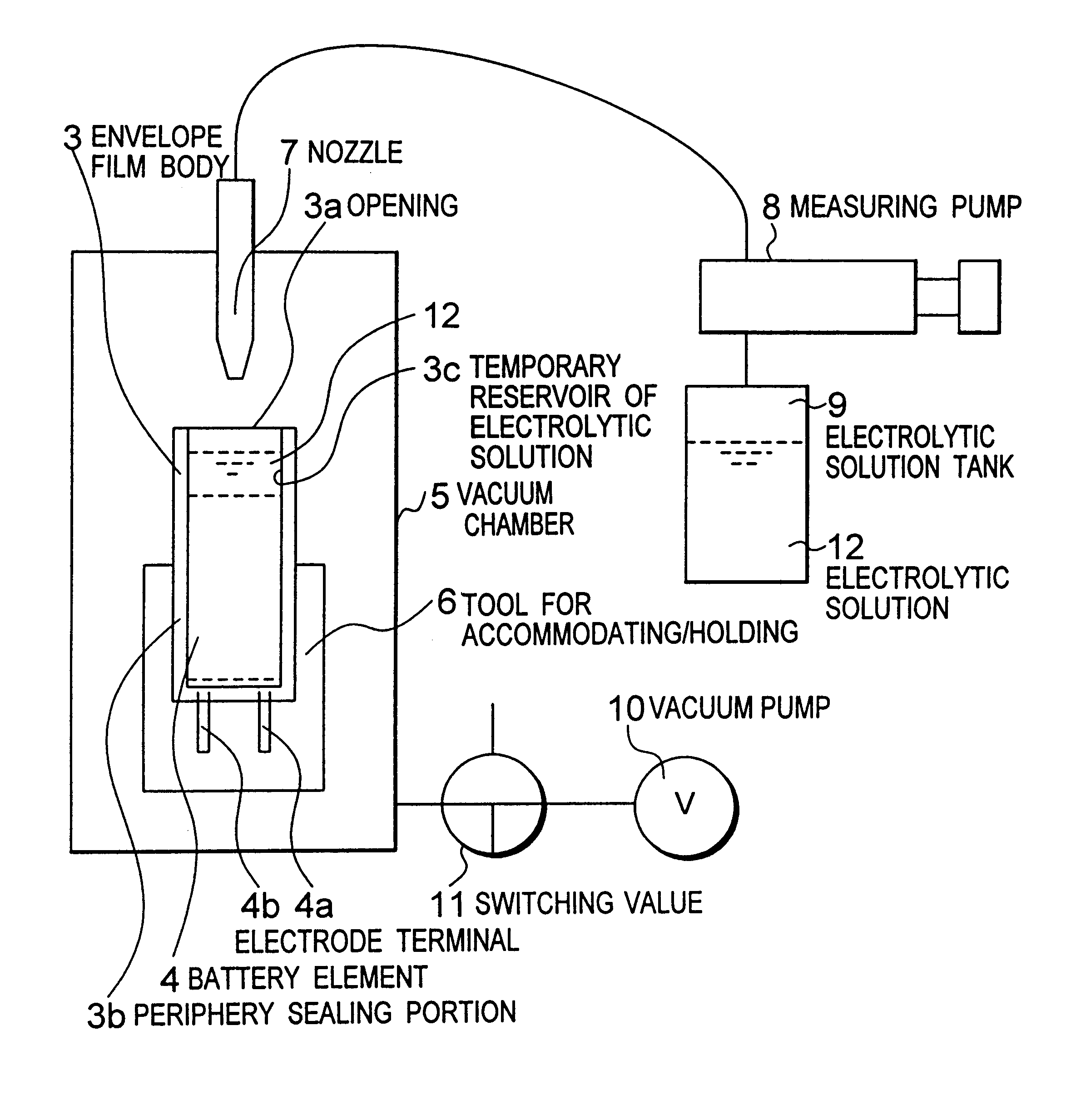
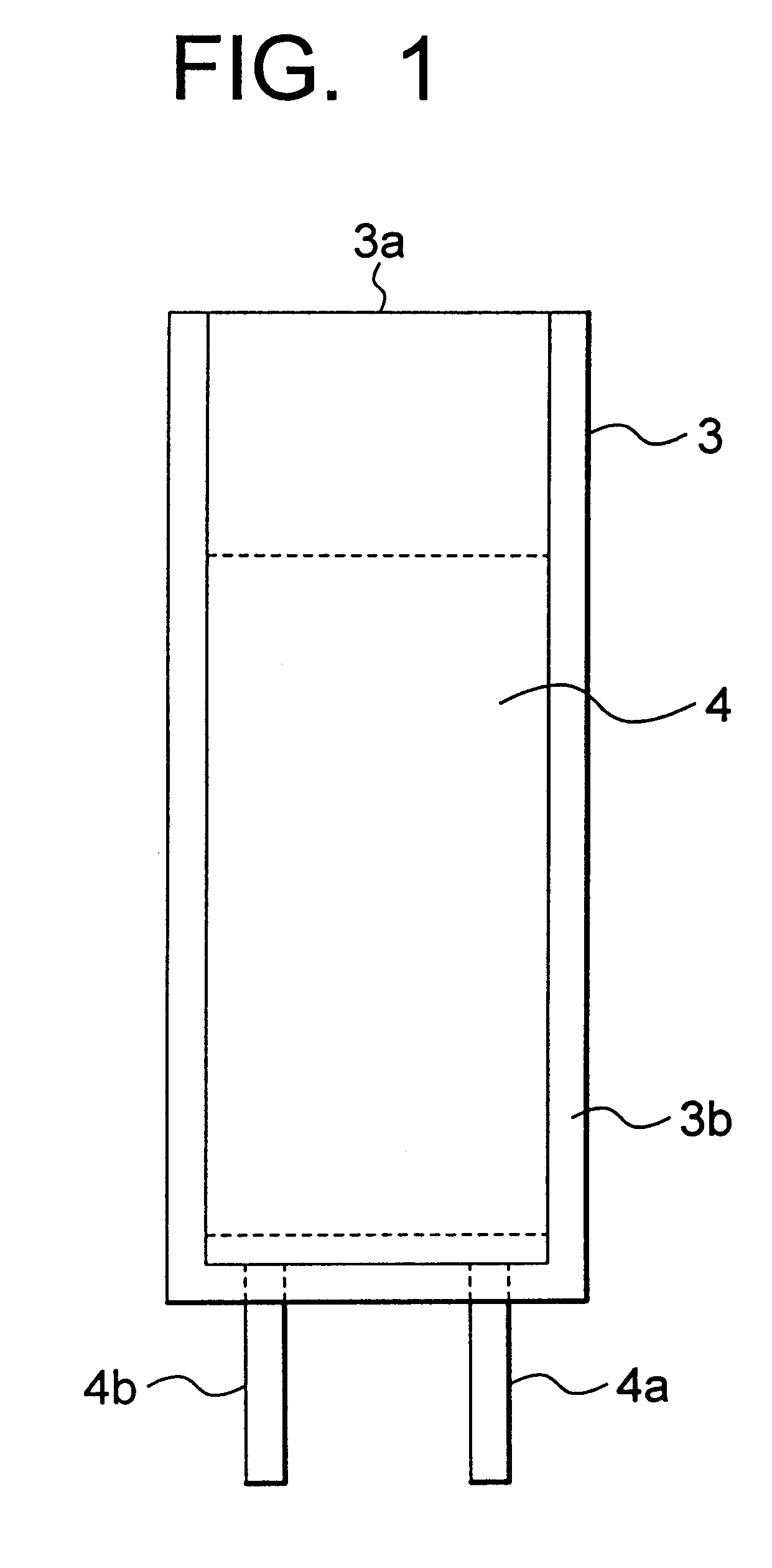
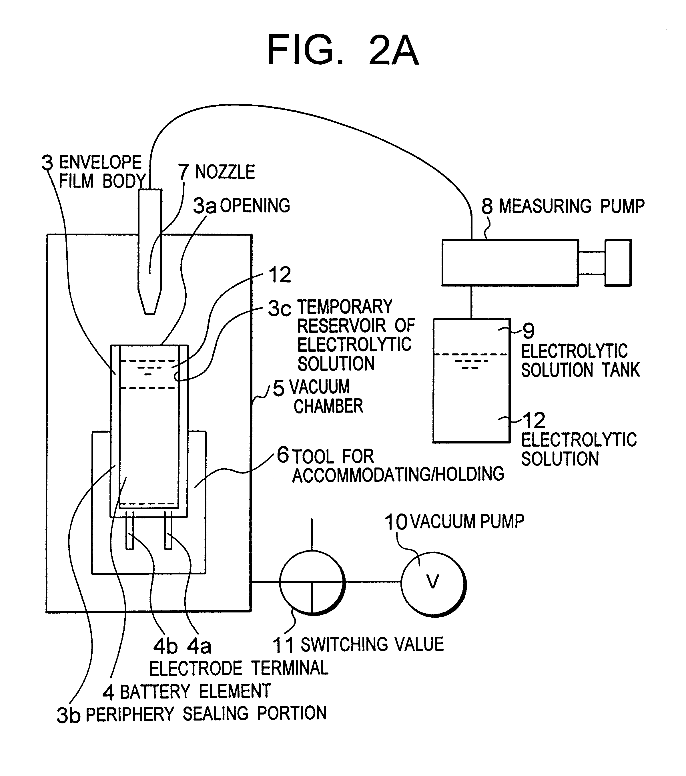
In the following, an embodiment will be explained with reference to FIG. 1 and FIGS. 2A to 2C.

FIG. 1 is a front view showing a substantial constitution of a battery before injection of an electrolytic solution. That is, the figure shows a state where a battery element 4 is accommodated in an envelope film body 3 provided with an opening 3a, which becomes an opening for injecting electrolytic solution, at one end side. Here, the envelope film body 3 is formed in a longer dimension than that of the accommodated battery element 4.

Here, the envelope film body 3 is made of a laminate film in which on both main surfaces of for instance an aluminum foil layers of polyethylene terephthalate resin are disposed, further on one surface thereof a layer of hot-melt resin (layer of for instance polypropylene resin) being disposed. The envelope film body 3 thus formed, with the layer of the hot-melt resin faced to each other, is laminated so as to interpose the battery element 4. One end thereof i...


PUM

PropertyMeasurementUnit
thicknessaaaaaaaaaa
shapeaaaaaaaaaa
dimensionaaaaaaaaaa

Abstract

This manufacturing method of batteries that comprises the steps of accommodating a battery element 4 in an envelope film body 3 of which one end side is opened to form an opening 3a for injecting an electrolytic solution; and sealing the opening 3a after the electrolytic solution 12 is injected from the opening 3a of the envelope film body 3; wherein an opening 3a side of the envelope film body 3 is made larger than a prescribed shape and dimension to use as a temporary reservoir region 3c of an injected electrolytic solution 12, after injection of a prescribed amount of the electrolytic solution 12 the region 3d of the prescribed shape and dimension being sealed and cut to form a battery. According to the method, a manufacturing method of batteries that can not only make smaller and lighter the batteries but also mass-produce batteries of high quality can be provided.

Description

The present inventions relates to a manufacturing method of batteries.DESCRIPTION OF THE RELATED ARTSo far, secondary batteries for instance such as non-aqueous solvent type batteries are in broad use as a power source for portable telephones, video cameras or the like. In batteries for power source, as the aforementioned instruments become smaller in size and higher in performance, demands on smaller size, lighter weight, higher voltage, larger capacity and so on are increasingly stronger. Corresponding to these demands, in for instance Japanese Patent Laid-open Application Nos. HEI 3-230474, HEI 3-225765 and so on, polymer batteries of approximately 1 mm thickness are disclosed.That is, in these batteries, a battery element, after aligning to accommodate in an envelope film body (exterior envelope body / bag body) having one open-end, is wrapped therewith. Then, from the opening thereof a prescribed electrolytic solution is injected. Thereafter, the opening is hot-melted to constitu...

Claims


Application Information

Patent Timeline
Patent Type & Authority Patents(United States)
IPC IPC(8): H01M2/36H01M10/36H01M2/02H01M2/00H01M10/38H01M10/40H01M10/05H01M10/0566H01M10/058H01M50/105H01M50/119H01M50/121H01M50/122H01M50/126H01M50/55H01M50/553H01M50/636H01M50/682H01M50/77
CPCH01M2/021H01M2/365H01M2/40H01M2/361H01M2/0207H01M2/0275Y10T29/4911H01M10/052Y02E60/10H01M50/636H01M50/77Y02P70/50H01M50/553H01M50/105H01M50/55H01M50/121H01M50/126H01M50/682H01M50/122H01M50/119
Inventor TAKAYAMA, GENTERUI, TOSHIYAKAWAMURA, NOBUO
Owner TOSHIBA BATTERY
Why Eureka
Try Eureka