Short pulse laser protection fly's eye lens

Inactive Publication Date: 2002-04-23
SMITH DAVID C
View PDF7 Cites 21 Cited by
  • Summary
  • Abstract
  • Description
  • Claims
  • Application Information

AI Technical Summary

Benefits of technology

Objects of the invention include provision of a simple, low-cost lens for protecting against short pulse laser radiation; a short pulse laser radiation lens being capable of implementation with f numbers higher than f-2; and a practical, effective lens for protecting against short pulse laser radiation.

Problems solved by technology

A problem with that invention is that the ratio of the aperture to the thickness of the lens implies either an extremely thick lens (on the order of several inches thick), or an f number which is difficult or impossible to practically achieve (being on the order of less than 1.2).

Method used


Image

  • Short pulse laser protection fly's eye lens
  • Short pulse laser protection fly's eye lens
  • Short pulse laser protection fly's eye lens

Examples


Embodiment Construction

The concept of the aforementioned patent is to focus the incoming laser radiation with sufficient magnification to increase the laser pulse energy to a high enough level so as to generate a laser induced aerosol breakdown which will absorb 99% or more of the laser energy and thereby protect the high gain optical system (eyes or equipment) from optical damage. The breakdown phenomenon results from a free electron accelerated by the laser radiation field, which gains sufficient energy to ionize an atom upon collision. This then becomes two electrons, and if the laser intensity is sufficiently high, leads to full ionization and, therefore, breakdown.

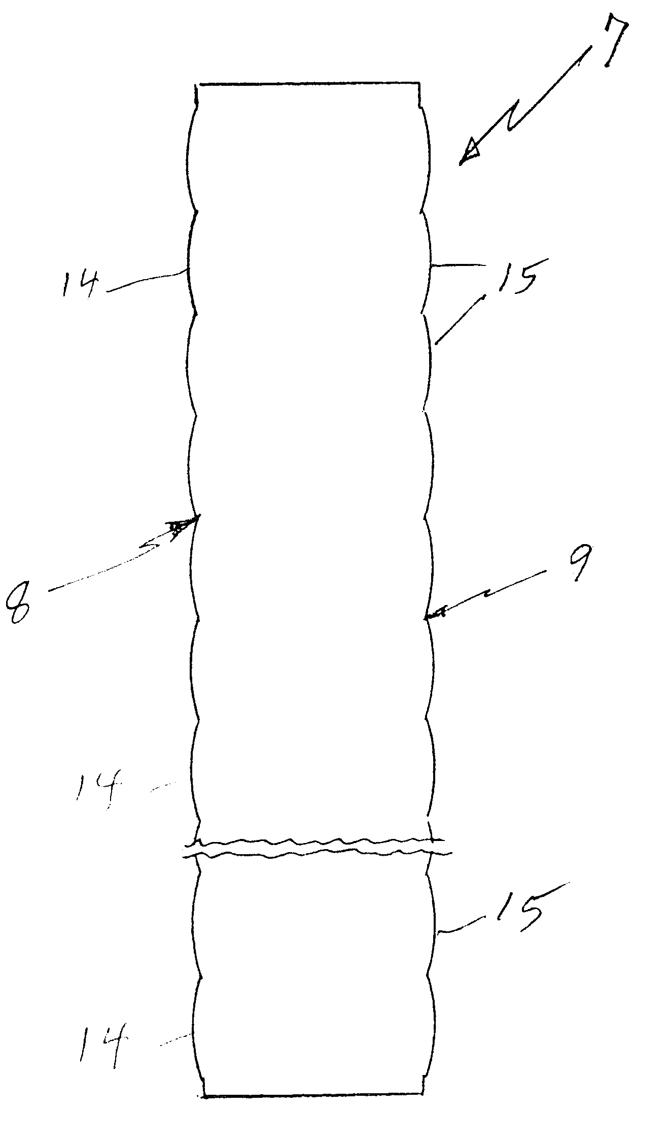
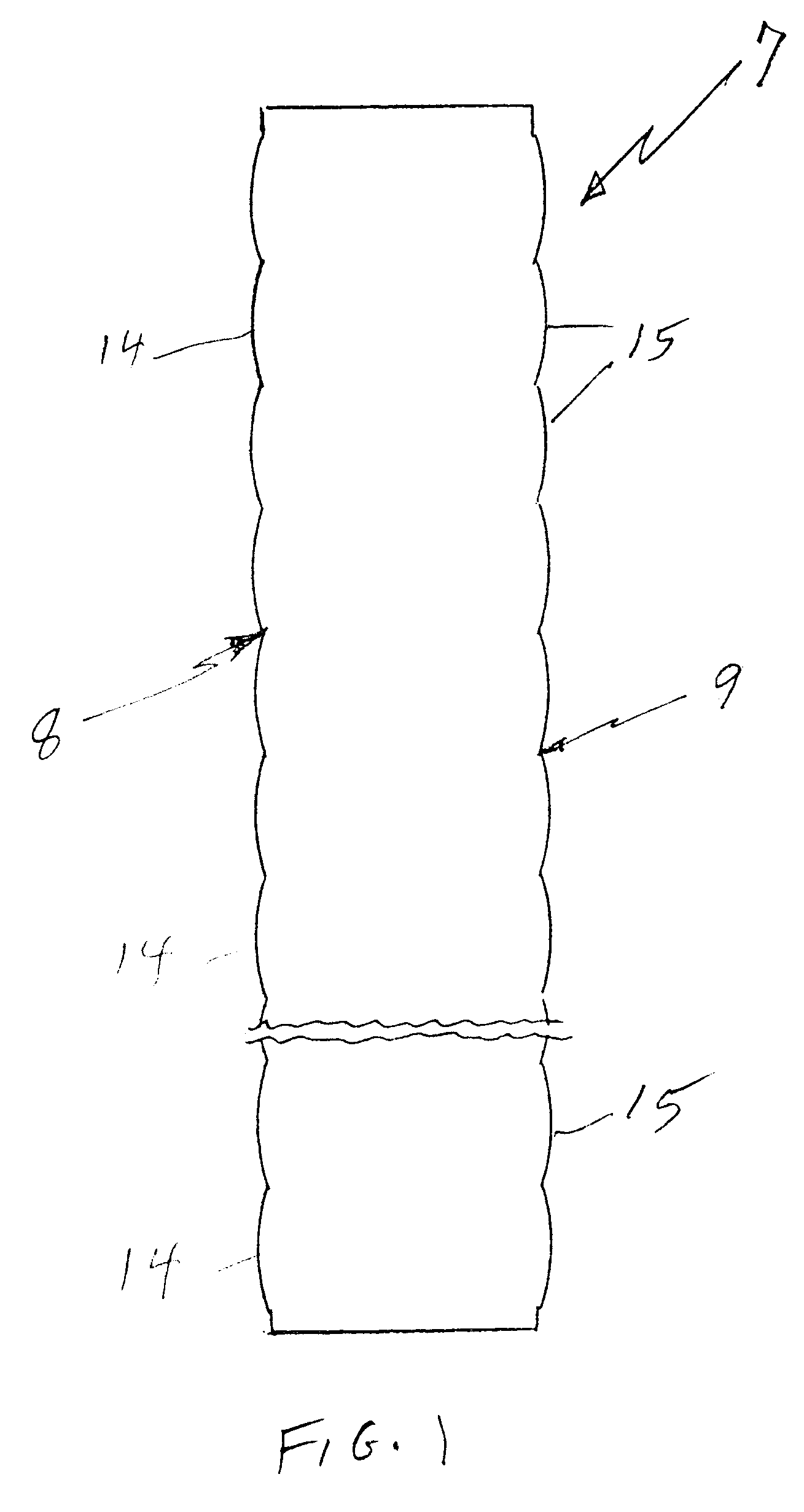
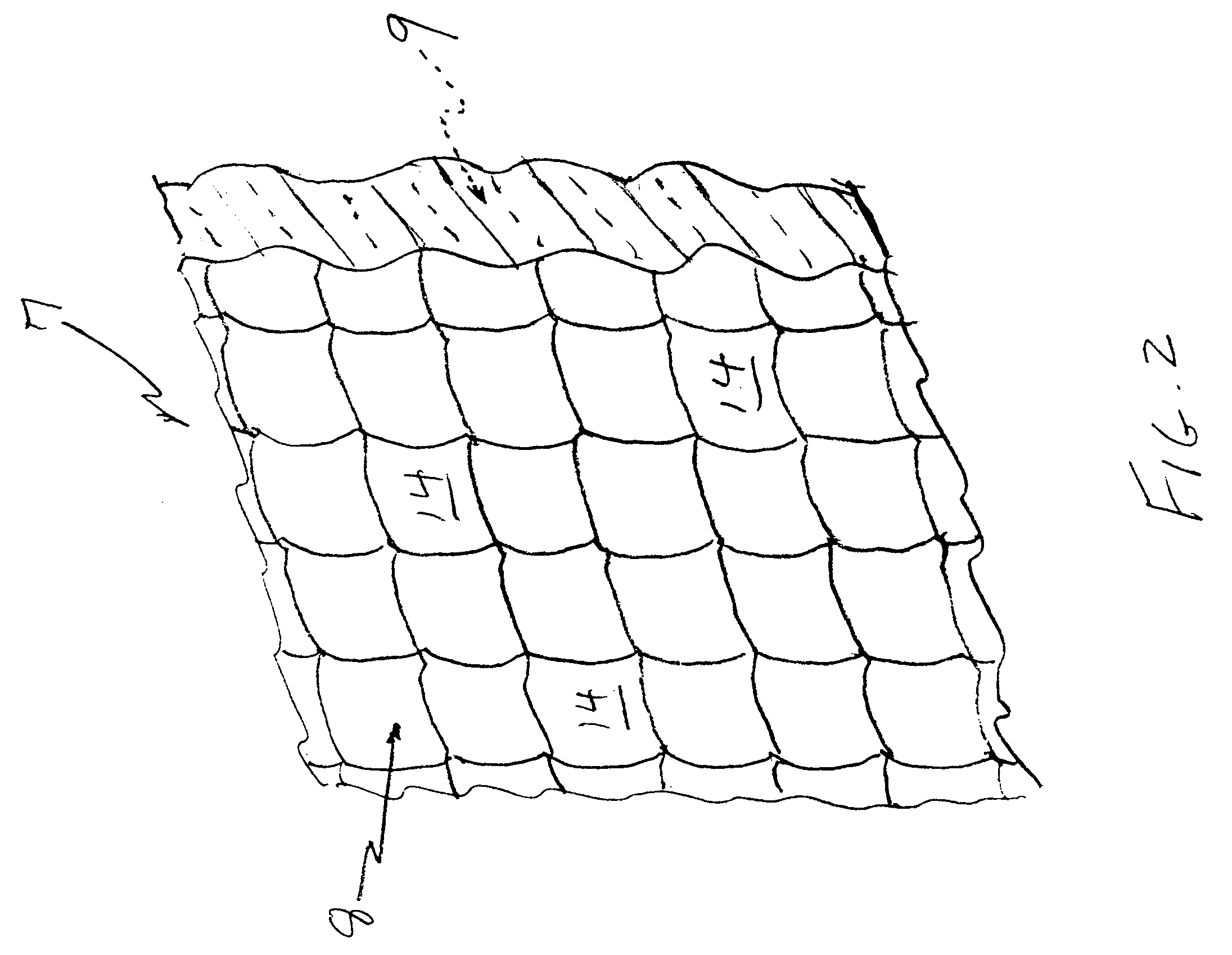
Referring to FIGS. 1 and 2, a lens array 7 in accordance with the invention has an optical entry surface 8 and an optical exit surface 9, each surface having formed therein a plurality of frusto-spherical, convex lenses 14, 15 formed therein.

As illustrated in FIG. 3, each pair of optical entry lens 14a and optical exit lens 15a correspond t...


PUM


Abstract

A lens array (7) has a plurality of frusto-spherical convex lenses (14, 15), formed in an optical entry surface (8) and an optical exit surface (9), focusing light rays (18, 19) near the center between each lens pair (14a, 15a) in an area (20) where the laser energy is focused sufficiently to induce vaporization resulting in aerosol breakdown which will absorb 99% or more of the laser energy, and thereby protect high gains optical equipment or eyes from optical damage.

Description

This invention relates to a protective lens array in which particle induced gas breakdown absorbs laser power.1. Background ArtU.S. Pat. No. 6,028,732 discloses a lens for protecting high gain optical systems (eyes or equipment) from laser radiation pulses of about one microsecond duration and less. One embodiment comprises a normal binocular system which focuses the radiation at a central point so as to vaporize an aerosol particle, thereby to induce an avalanche of ionization, commonly known as gas breakdown, as reported by Smith, David C., "Gas Breakdown Initiated by Laser Radiation Interaction with Aerosols and Solid Surfaces", J. of Applied Physics, June 1977, p. 2217. The binocular system may comprise a solid lens material such as glass or carbonate, having entry and exit binocular lenses formed at the ends thereof, the solid being laden with aerosol particles.A problem with that invention is that the ratio of the aperture to the thickness of the lens implies either an extreme...

Claims


Application Information

Patent Timeline
IPC IPC(8): G02B3/00G02B27/30
CPCG02B3/0056G02B27/30G02B3/0062
Inventor SMITH, DAVID C.
Owner SMITH DAVID C
Why Eureka
Try Eureka