Windmill and windmill control method

a control method and windmill technology, applied in the field of windmills, can solve the problems of large windmills, complicated mechanisms, and restricted windmill rotation positions,

Inactive Publication Date: 2002-04-30
HIRAI TETSUO
View PDF10 Cites 137 Cited by
  • Summary
  • Abstract
  • Description
  • Claims
  • Application Information

AI Technical Summary

Benefits of technology

It is another object of the present invention to provide highly efficient wind receiving blades control by rotating the wind receiving blades in directions most efficient for receiving wind, freely positioning the rotation of the wind receiving blades irrespectively of the revolution of the revolution shaft and allowing the wind receiving blades to freely invert and stop.

Problems solved by technology

Due to this, the rotation of the wind receiving blades is specified univocally based on their mechanical coupling states and the setting of the rotating positions of the wind receiving blades has been quite restricted.
In this connection, the reduction of vibration and noise is regarded as a challenge for the windmills.
This inevitably leads to a larger windmill and more complex mechanisms.

Method used


Image

  • Windmill and windmill control method
  • Windmill and windmill control method
  • Windmill and windmill control method

Examples


Embodiment Construction

First, a windmill according to the present invention will be described hereinafter in detail with reference to the accompanying drawings.

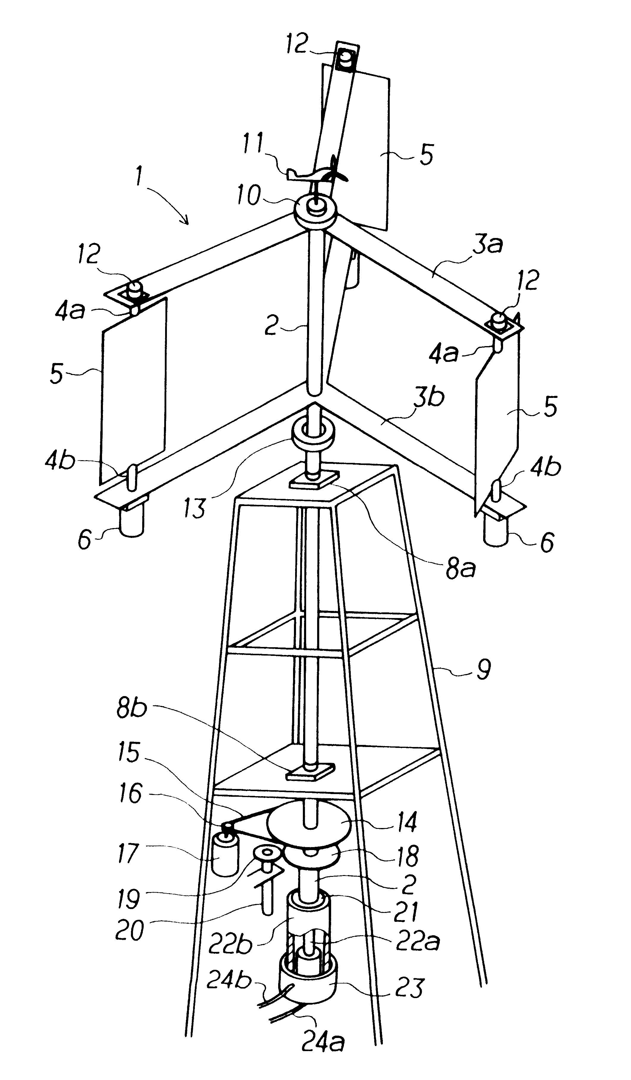
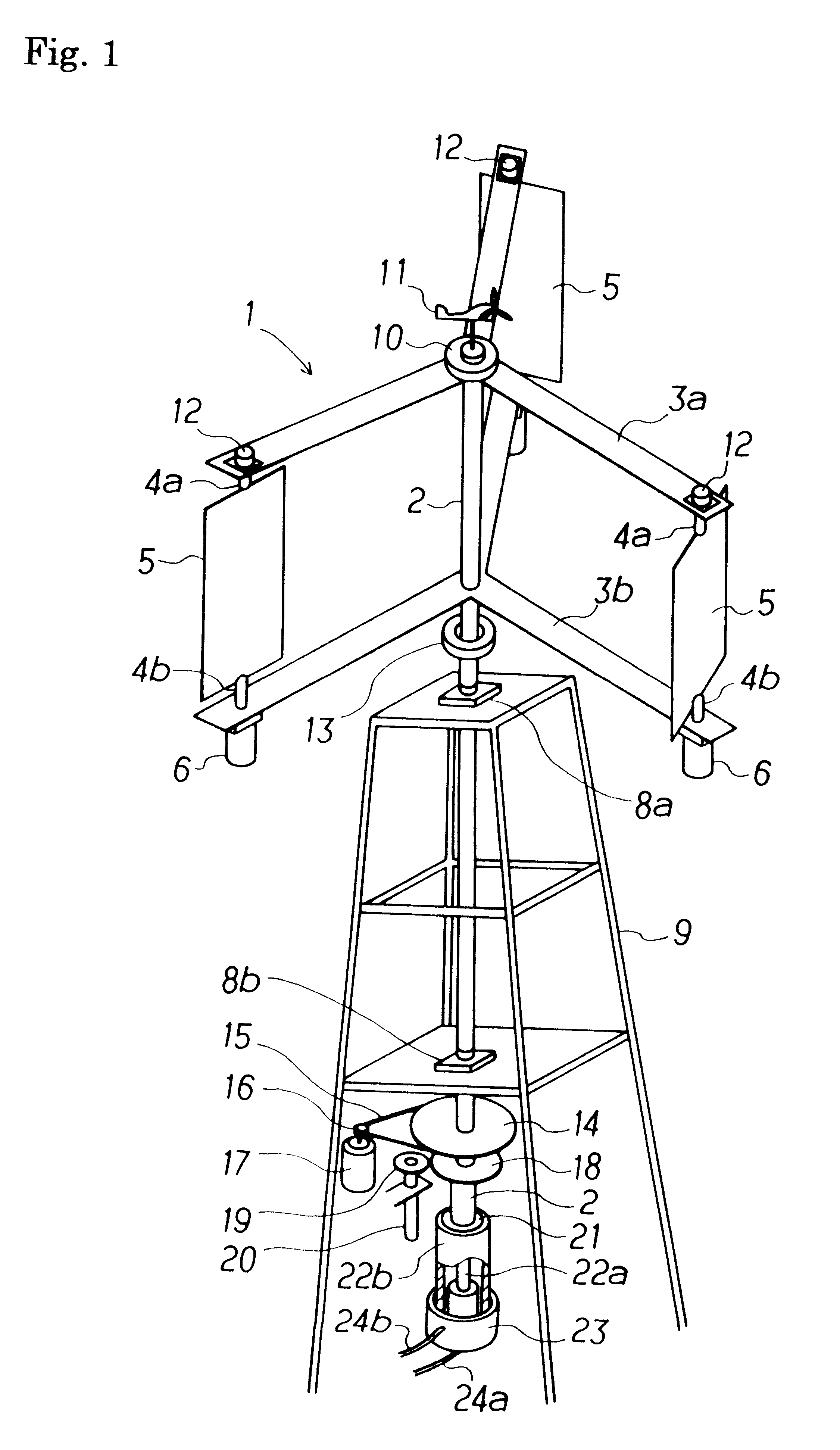
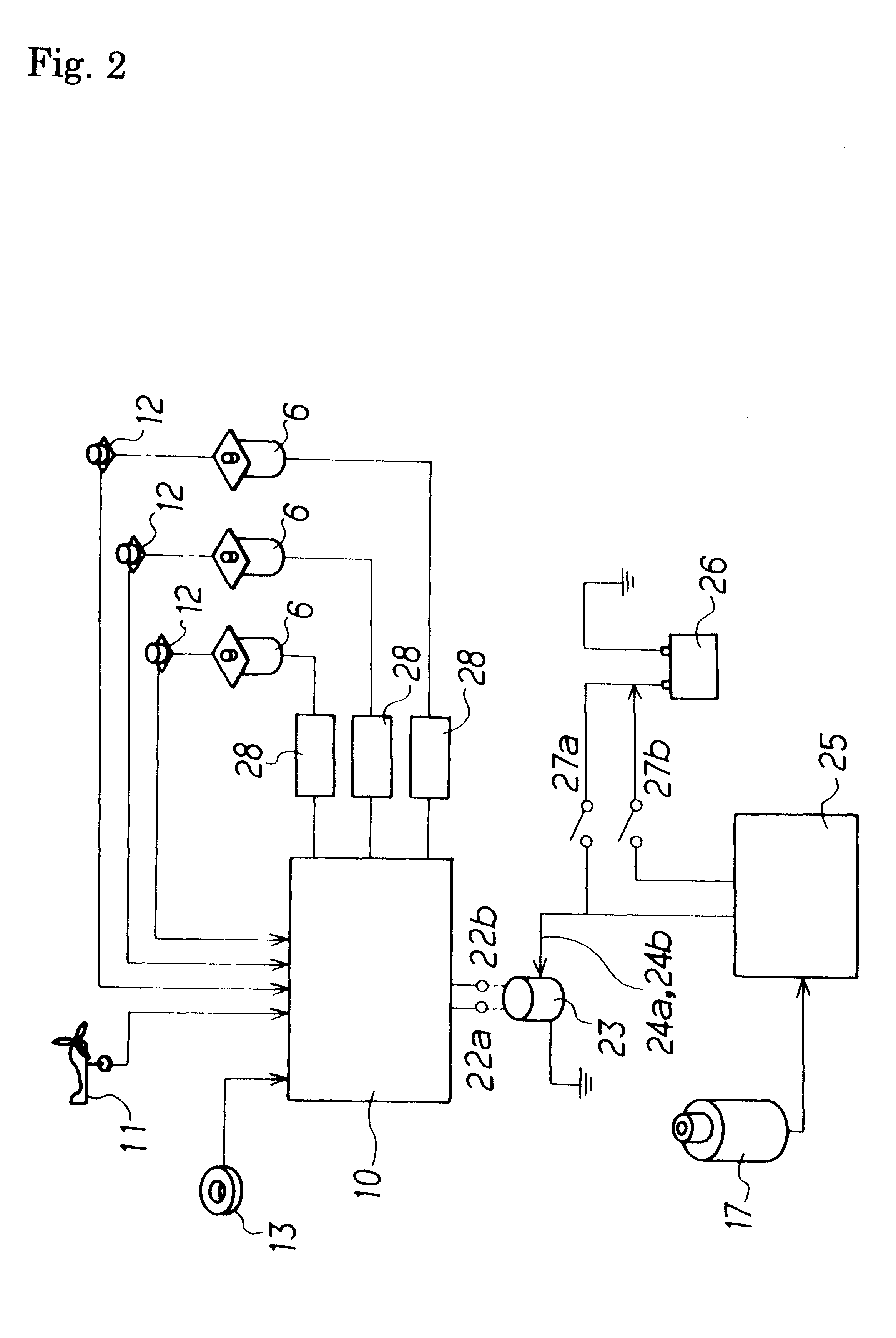
In FIG. 1, a windmill 1 is comprised of a revolution shaft 2, a plurality of pairs of upper and lower pivotal support rods 3a and 3b provided around the revolution shaft 2, and wind receiving blades 5 respectively and rotatably set between the pairs of pivotal support rods 3a and 3b with wind receiving blade shafts 4a and 4b. Also, servo motors 6 are fixedly provided on the lower parts of the pivotal support rods 3b of the windmill 1, respectively. The output shaft (not shown in FIG. 1) of each of the servo motors 6 is coupled to the corresponding wind receiving blade shaft 4b so as to be freely controllable over the direction of the corresponding wind receiving blade 5.

The revolution shaft 2 is a hollow shaft with an appropriate length and the important parts thereof are pivotally supported by bearings 8a and 8b. The bearings 8a and 8b, which are ...


PUM


Abstract

A windmill includes a freely rotatable revolution shaft, a plurality of pairs of pivotal support rods provided at the revolution shaft, and wind receiving blades respectively and rotatably set between the pivotal support rods with wind receiving blade shafts. The windmill is applied to the driving of a lifting pump, a generator and the like by employing revolution driving force. An anemometer / anemoscope measures wind velocity and direction. A servo motor controls the direction of the wind receiving blades based on the detected velocity and direction. Various methods of control are also provided.

Description

1. Field of the InventionThe present invention relates to a windmill consisting of a freely rotatable revolution shaft, a plurality of pairs of pivotal support rods provided at the revolution shaft, and wind receiving blades respectively and rotatably set between the pivotal support rods with wind receiving blade shafts. The windmill is applied to the driving of a lifting pump, a generator and the like by employing revolution driving force.2. Prior ArtAs windmills of this type, there have been hitherto known those disclosed by, for example, Japanese Patent Unexamined Application Publication Nos. 55-131585, 57-372, 57-56674 and 11-117850.Japanese Patent Unexamined Application Publication No. 55-131585 discloses the structure of a windmill which consists of a plurality of blades rotating on their own shafts and revolving around a revolution main shaft, gears provided at the rotary shafts of these blades, respectively and gears provided at the main shaft of the windmill. The gears are ...

Claims


Application Information

Patent Timeline
Patent Type & Authority Patents(United States)
IPC IPC(8): F03D7/06F03D3/06F03D7/00F03D3/00
CPCF03D3/068F03D7/06Y02E10/74F05B2270/32F05B2270/321F05B2260/507
Inventor HIRAI, TETSUO
Owner HIRAI TETSUO
Why Eureka
Try Eureka