Seamed sail and method of manufacture

a technology applied in the field of seams and sails, can solve the problems of difficult seams, complex shape design, and need to cut sails

Inactive Publication Date: 2002-05-07
KEIRE FRED AIVARS
View PDF21 Cites 33 Cited by
  • Summary
  • Abstract
  • Description
  • Claims
  • Application Information

AI Technical Summary

Benefits of technology

Accordingly, a sail with the pre-shaped panels, e.g. for scrim reinforced substrates, need not be made on a curved mold but can now be made on a flat surface. Such production method significantly reduces the capital investment and mold fabrication as well as mold adjustments needed for each sail. Moreover, sail panels produced according to the present invention are nested in an improved manner. These panels can be seamed in a pre-selective, i.e., pre-designed manner. Hence, sail shape design may be made by an improved combination of luff curve shaping and broad seaming and gluing of the panels.
Sails produced by the present method are fiber tension controlled and are capable of being made in an unlimited variety of primary and secondary oriented yarn-panel layouts allowing design freedom for further exploring and developing yarn layouts achieving optimum "balance" properties.

Problems solved by technology

A major problem for the monolithic mold made sails such as the North Sails 3DL.TM. sails has been reshaping of the sail after manufacture.
While some reshaping has been possible based on varying the luff S curve, the lack of panels has made it necessary to cut the sail and introduce cut panels.
Such post fabrication of panels has made it difficult to form a proper seam(s) and gluing typically must be done film to film.
In the 3DL.TM. method disclosed in U.S. Pat. No. 5,097,784, the complexity of shape design resides in the mold contour control; the pre-shaping of the film and scrim in panels which then must be placed on the mold; the inability to vary economically the yarn content or mixture from place to place in the sail as needed; the awkward manipulation of yarns in the corners and at the edges of the sail; the complexity in the fiber orientation to produce an approximation of the primary and secondary load paths; the shape adjustments when cutting the sail etc., etc.
Such production method significantly reduces the capital investment and mold fabrication as well as mold adjustments needed for each sail.

Method used


Image

  • Seamed sail and method of manufacture
  • Seamed sail and method of manufacture
  • Seamed sail and method of manufacture

Examples


Embodiment Construction

With reference to the drawings schematically illustrating various embodiments of the invention and without limiting other aspects of the invention:

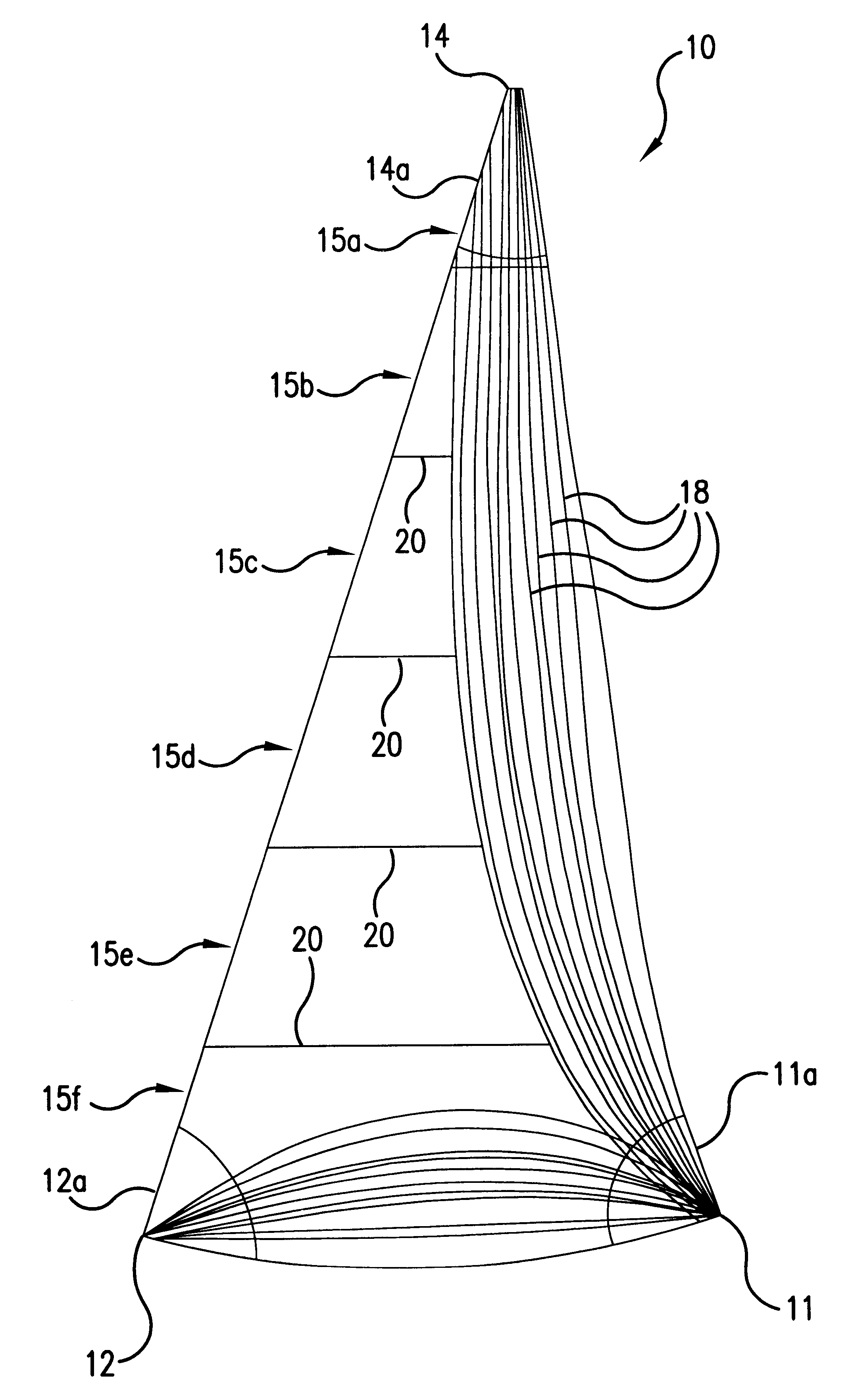
FIG. 1 illustrates in plan view a jib or genoa sail partially fabricated;

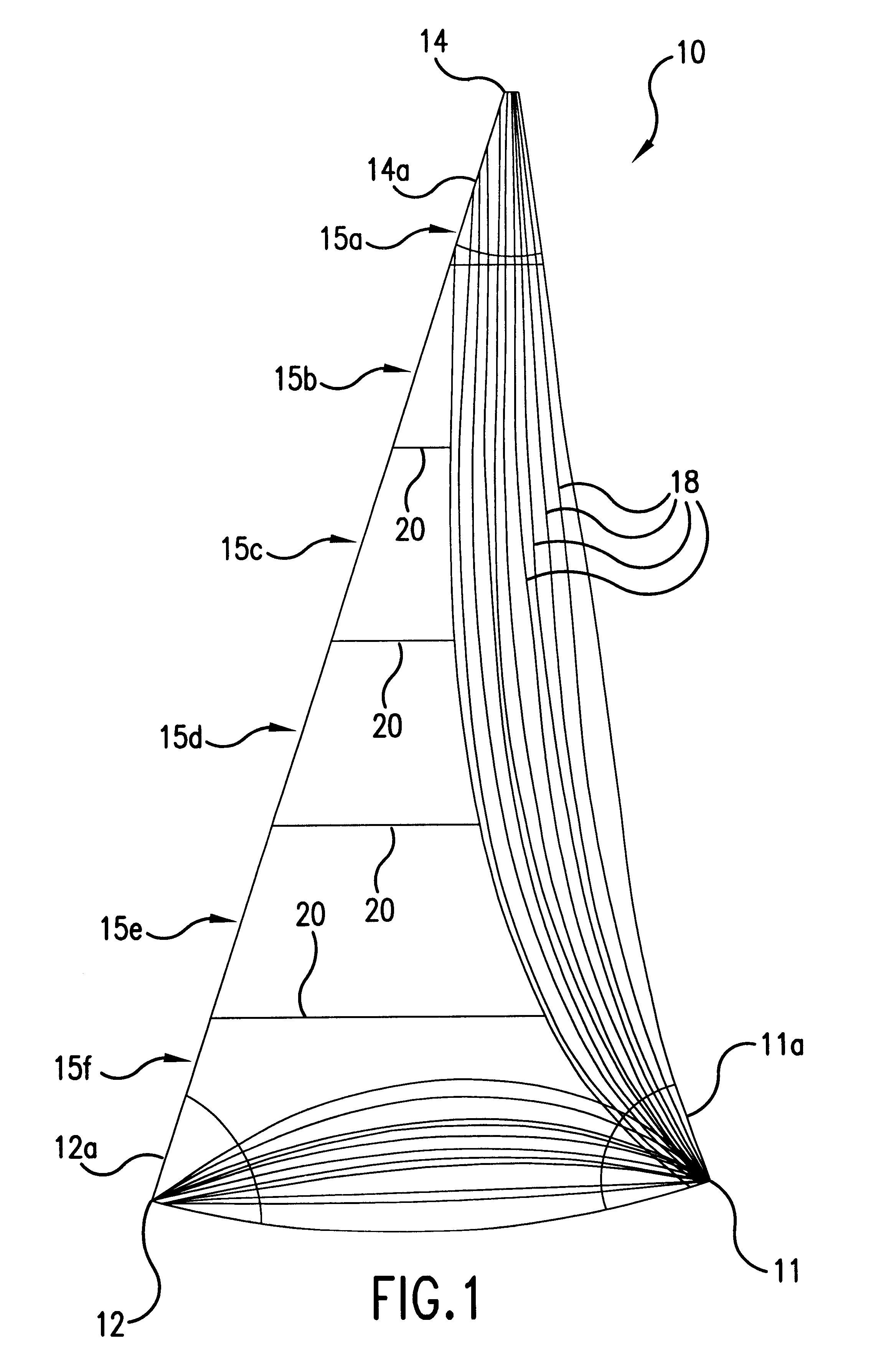
FIG. 2 illustrates in plan view a mainsail with various panel arrangements;

FIG. 3 illustrates in a plan view precursor panels and seams for a jib sail made on a flat table;

FIG. 3A illustrates in a plan view an embodiment for reversing directions at a corner of a sail;

FIG. 3B illustrates schematically in a cross-sectional view a seam before it is glued together;

FIG. 3C illustrates schematically in a cross-sectional view a finished, glued seam;

FIG. 4 illustrates schematically in a top plan view a table with associated gantry and turret devices for laying down continuous filament yarns on a sail precursor shape;

FIG. 5 illustrates schematically in a partial left-hand side view a gantry and a turret shown in FIG. 4 including a yarn dispensing device;

FIG. 6 illustrates in ...


PUM

PropertyMeasurementUnit
lengthaaaaaaaaaa
lengthaaaaaaaaaa
heat activatableaaaaaaaaaa

Abstract

A seamed sail made from a full size precursor sail of yarn oriented load path specific type which is thereafter cut and seamed; a method for making the sail and an apparatus for it.

Description

BACKGROUND FOR THE INVENTIONIn chronological order in the past century, sails have been made of woven textile materials. Base fibers for these textile materials were derived from natural polymers, i.e., cellulose, of which cotton and linen were preeminent. In general, the fibers in these textile yarns used for weaving sailcloth were of short length as it is typically found in natural polymers. However, significant advantage in sails was realized by longer length fibers and high quality sails were sold as being made of long length "Egyptian cotton" yarns.With the advent of synthetic fibers, that is an extruded bundle of "continuous" filaments for yarns, the length of fibers in yarns became immaterial, as typically all yarns were a bundle of "mono" filament yarns of substantial "fiber" length. Chopped fiber yams or "spun yams" or "staple" were not used in sailcloth. Hence, the meaning of monofilament yarns, continuous filament fibers, and yarns became interchangeable for sail making p...

Claims


Application Information

Patent Timeline
Patent Type & Authority Patents(United States)
IPC IPC(8): B29C65/00B63H9/06B63H9/00
CPCB63H9/0657B63H2009/0678B29C66/1248B29C66/43B29C65/4815B29C66/729B29L2031/3067B29C65/48B29C66/723B63H9/0678B63H9/067
Inventor KEIRE, FRED AIVARS
Owner KEIRE FRED AIVARS
Why Eureka
Try Eureka